Nissan Juke Service and Repair Manual : Door cable
Exploded View
LEFT SIDE
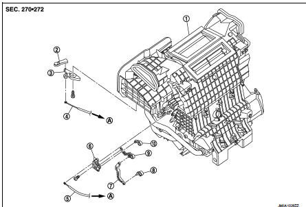
1. Heater unit assembly
2. Intake door lever
3. Intake door link
4. Intake door cable
5. Air mix door cable
6. Air mix door link
7. Air mix door rod
8. Lower air mix door lever
9. Upper air mix door lever
10. Max. cool door
A. To A/C control
RIGHT SIDE
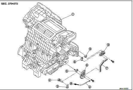
1. Heater unit assembly
2. Mode door cable
3. Foot door lever
4. Foot door link
5. Side ventilator door lever
6. Mode door main link
7. Mode door main link adapter rod
8. Center ventilator door lever
9. Defroster door lever
10. Mode door main link adapter
A. To A/C control
Intake door cable : Removal and Installation
REMOVAL
1. Disconnect intake door cable from A/C control. Refer to HAC-308, "Exploded View".
2. Remove instrument lower panel LH. Refer to IP-13, "Removal and Installation".
(LHD models)
3. Remove glove box assembly. Refer to IP-13, "Removal and Installation". (RHD
models)
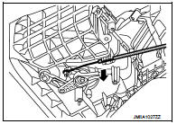
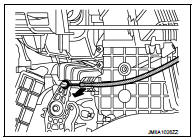
4. Disconnect intake door cable from heater unit assembly as
shown by the arrow in the figure, and then remove intake door
cable.
INSTALLATION
Install in the reverse order of removal.
Mode door cable : Removal and Installation
REMOVAL
1. Disconnect mode door cable from A/C control. Refer to HAC-308, "Exploded View".
2. Remove glove box assembly. Refer to IP-13, "Removal and Installation". (LHD
models)
3. Remove instrument panel RH. Refer to IP-13, "Removal and Installation". (RHD
models)
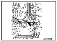
4. Disconnect mode door cable from heater unit assembly as
shown by the arrow in the figure, and then remove mode door
cable.
INSTALLATION
Install in the reverse order of removal.
Air mix door cable : Removal and Installation
REMOVAL
1. Disconnect air mix door cable from A/C control. Refer to HAC-308, "Exploded View".
2. Remove instrument panel LH. Refer to IP-13, "Removal and Installation". (LHD
models)
3. Remove glove box assembly. Refer to IP-13, "Removal and Installation". (RHD
models)
4. Disconnect air mix door cable from heater unit assembly as
shown by the arrow in the figure, and then remove air mix door
cable.
INSTALLATION
Install in the reverse order of removal.
 Blower fan resistor
Exploded View
1. Heater unit assembly
2. Fan control amp.*1
3. Blower fan resistor*2
4. Blower motor
5. Blower motor cover
• *1: Automatic air conditioner
• *2: Manual air conditioner or M ...
 Interior
...
Other materials:
Types of tires
WARNING
• When changing or replacing tires, be sure all four tires are of the same
type (Example: Summer, All Season or Snow) and construction. A NISSAN dealer may
be able to help you with information about tire type, size, speed rating and availability.
• Replacement tires may have a lower sp ...
Unlock sensor
Component Function Check
1.CHECK FUNCTION
1. Select “DOOR LOCK” of “BCM” using CONSULT-III.
2. Select “LOCK STATUS” in “DATA MONITOR” mode.
3. Check that the function operates normally according to the following
conditions.
Is the inspection result normal?
YES >> Unlock sensor is OK. ...
Key switch
Component Function Check
1.CHECK FUNCTION
1. Select “DOOR LOCK” of “BCM” using CONSULT-III.
2. Select “KEY ON SW” in “DATA MONITOR” mode.
3. Check that the function operates normally according to the following
conditions.
Is the inspection result normal?
YES >> Key switch is OK.
N ...
