Nissan Juke Service and Repair Manual : Door cable
Exploded View
LEFT SIDE
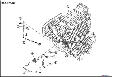
1. A/C unit assembly
2. Intake door lever
3. Intake door link
4. Intake door cable
5. Air mix door cable
6. Air mix door link
7. Air mix door rod
8. Lower air mix door lever
9. Upper air mix door lever
10. Max. cool door
A. To A/C control
RIGHT SIDE
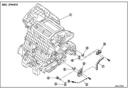
1. A/C unit assembly
2. Mode door cable
3. Foot door lever
4. Foot door link
5. Side ventilator door lever
6. Mode door main link
7. Mode door main link adapter rod
8. Center ventilator door lever
9. Defroster door lever
10. Mode door main link adapter
A. To A/C control
Intake door cable : Removal and Installation
REMOVAL
1. Disconnect intake door cable from A/C control. Refer to HAC-308, "Exploded View".
2. Remove instrument lower panel LH. Refer to IP-13, "Removal and Installation".
(LHD models)
3. Remove glove box assembly. Refer to IP-13, "Removal and Installation". (RHD
models)
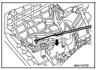
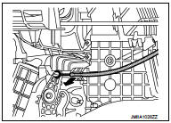
4. Disconnect intake door cable from A/C unit assembly as shown
by the arrow in the figure, and then remove intake door cable.
INSTALLATION
Install in the reverse order of removal.
Mode door cable : Removal and Installation
REMOVAL
1. Disconnect mode door cable from A/C control. Refer to HAC-308, "Exploded View".
2. Remove glove box assembly. Refer to IP-13, "Removal and Installation". (LHD
models)
3. Remove instrument panel RH. Refer to IP-13, "Removal and Installation". (RHD
models)
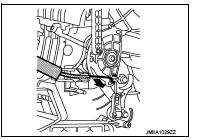
4. Disconnect mode door cable from A/C unit assembly as shown
by the arrow in the figure, and then remove mode door cable.
INSTALLATION
Install in the reverse order of removal.
Air mix door cable : Removal and Installation
REMOVAL
1. Disconnect air mix door cable from A/C control. Refer to HAC-308, "Exploded View".
2. Remove instrument panel LH. Refer to IP-13, "Removal and Installation". (LHD
models)
3. Remove glove box assembly. Refer to IP-13, "Removal and Installation". (RHD
models)
4. Disconnect air mix door cable from A/C unit assembly as shown
by the arrow in the figure, and then remove air mix door cable.
INSTALLATION
Install in the reverse order of removal.
 Blower fan resistor
Exploded View
1. A/C unit assembly
2. Fan control amp.*1
3. Blower fan resistor*2
4. Blower motor
5. Blower motor cover
• *1: Automatic air conditioner
• *2: Manual air conditioner
Remov ...

Other materials:
Stall test
Work Procedure
INSPECTION
1. Check the engine oil level. Replenish if necessary. Refer to LU-25,
"Inspection".
2. Check for leak of the CVT fluid. Refer to TM-480, "Inspection".
3. Drive for about 10 minutes to warm up the vehicle so that the CVT fluid
temperature is 50 t ...
Removal and installation
Road wheel tire assembly
Exploded View
1. Tire assembly
: N·m (kg-m, ft-lb)
Removal and Installation
REMOVAL
1. Remove wheel nuts.
2. Remove tire assembly.
INSTALLATION
Install in the reverse order of removal.
Inspection
ALUMINUM WHEEL
1. Check tires for wear and improper inflation.
...
Keys
A key number plate is supplied with your keys.
Record the key number and keep it in a safe place (such as your wallet), not
in the vehicle. If you lose your keys, see a NISSAN dealer for duplicates by using
the key number. NISSAN does not record any key numbers so it is very important to
keep ...
