Nissan Juke Service and Repair Manual : Door cable
Exploded View
LEFT SIDE
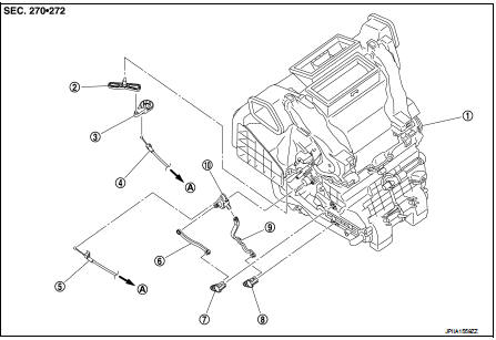
1. A/C unit assembly
2. Intake door lever
3. Intake door link
4. Intake door cable
5. Air mix door cable
6. Upper air mix door rod
7. Upper air mix door lever
8. Lower air mix door lever
9. Lower air mix door rod
10. Air mix door link
A. To A/C control
RIGHT SIDE
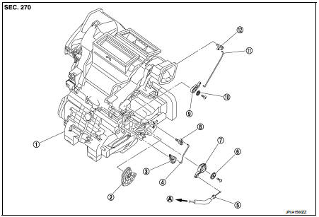
1. A/C unit assembly
2. Main link
3. Sub defroster door link
4. Sub defroster door rod
5. Mode door cable
6. Plate
7. Mode link
8. Sub defroster door lever
9. Center ventilator and defroster door link
10. Plate
11. Center ventilator and defroster door rod
12. Center ventilator and defroster door lever
A. To A/C control
Intake door cable : Removal and Install
REMOVAL
1. Disconnect intake door cable from A/C control. Refer to HAC-239, "Exploded View".
2. Remove instrument lower panel LH. Refer to IP-13, "Removal and Installation".
(LHD models)
3. Remove glove box assembly. Refer to IP-13, "Removal and Installation". (RHD
models)
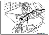
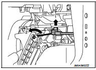
4. Disconnect intake door cable from A/C unit assembly as shown
by the arrow in the figure, and then remove intake door cable.
INSTALLATION
Install in the reverse order of removal.
Mode door cable : Removal and Installation
REMOVAL
1. Disconnect mode door cable from A/C control. Refer to HAC-239, "Exploded View".
2. Remove glove box assembly. Refer to IP-13, "Removal and Installation". (LHD
models)
3. Remove instrument panel RH. Refer to IP-13, "Removal and Installation". (RHD
models)
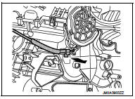
4. Disconnect mode door cable from A/C unit assembly as shown
by the arrow in the figure, and then remove mode door cable.
INSTALLATION
Install in the reverse order of removal.
Air mix door cable : Removal and Installation
REMOVAL
1. Disconnect air mix door cable from A/C control. Refer to HAC-239, "Exploded View".
2. Remove instrument panel LH. Refer to IP-13, "Removal and Installation". (LHD
models)
3. Remove glove box assembly. Refer to IP-13, "Removal and Installation". (RHD
models)
4. Disconnect air mix door cable from A/C unit assembly as shown
by the arrow in the figure, and then remove air mix door cable.
INSTALLATION
Install in the reverse order of removal.
 Blower fan resistor
Exploded View
1. A/C unit assembly
2. Blower fan resistor*1
3. Sub harness*1
4. Power transistor*2
5. Sub harness*2
6. Blower motor
• *1: Manual air conditioner
• *2: Automatic air condi ...

Other materials:
Compression pressure
Inspection
1. Warm up engine thoroughly. Then, stop it.
2. Release fuel pressure. Refer to EC-551, "Work Procedure".
3. Remove ignition coil and spark plug from each cylinder. Refer to EM-178,
"Exploded View".
4. Connect engine tachometer (not required in use of CONSULT-III ...
Super lock actuator
Driver side
DRIVER SIDE : Component Function Check
1.CHECK FUNCTION
1. Select “DOOR LOCK” of “BCM” using CONSULT-III.
2. Select “SUPER LOCK” in “ACTIVE TEST” mode.
3. Check that the function operates normally according to the following
conditions.
Is the inspection result normal?
YES > ...
Rapid air pressure loss
Rapid air pressure loss or a “blow-out” can occur if the tire is punctured or
is damaged due to hitting a curb or pothole. Rapid air pressure loss can also be
caused by driving on underinflated tires.
Rapid air pressure loss can affect the handling and stability of the vehicle,
especially at ...
