Nissan Juke Service and Repair Manual : Diagnosis and repair workflow
Gasoline engine models
GASOLINE ENGINE MODELS : Work Flow
OVERALL SEQUENCE
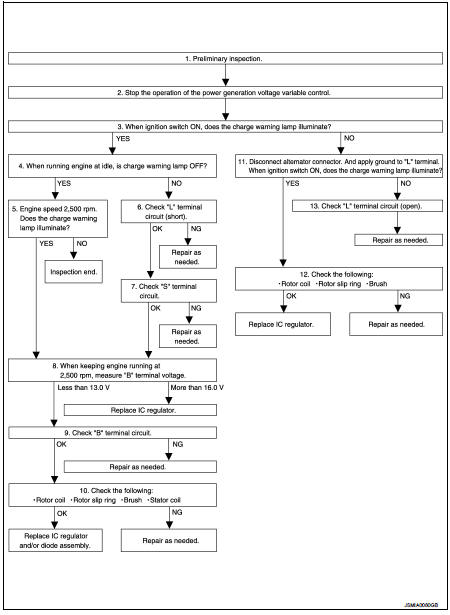
DETAILED FLOW
1.PRELIMINARY INSPECTION
Perform the preliminary inspection. Refer to CHG-17, "Inspection Procedure".
Models with battery current sensor>>GO TO 2.
Models without battery current sensor>>GO TO 3.
2.STOP POWER GENERATION VOLTAGE VARIABLE CONTROL SYSTEM
Stop the operation of the power generation voltage variable control in either of the following procedures.
• After selecting “ENGINE” of “SELECT SYSTEM” using CONSULT-III, set the DUTY value of “ALTERNATOR DUTY” to 0 % by selecting “ALTERNATOR DUTY” of “Active Test”. Continue “Active Test” until the end of inspection. (When the DUTY value is 0 or 100 %, the normal power generation is performed according to the characteristic of the IC regulator of the alternator.) • Turn the ignition switch OFF, and disconnect the battery current sensor connector. [However, DTC (P1550 - P1554) of the engine might remain. After finishing the inspection, connect the battery current sensor connector and erase the self-diagnostic results history of the engine using CONSULT-III.] >> GO TO 3.
3.INSPECTION WITH CHARGE WARNING LAMP (IGNITION SWITCH IS ON)
Turn the ignition switch ON.
Does the charge warning lamp illuminate? YES >> GO TO 4.
NO >> GO TO 11.
4.INSPECTION WITH CHARGE WARNING LAMP (IDLING)
Start the engine and run it at idle.
Does the charge warning lamp turn OFF? YES >> GO TO 5.
NO >> GO TO 6.
5.INSPECTION WITH CHARGE WARNING LAMP
Increase and maintain the engine speed at 2,500 rpm.
Does the charge warning lamp illuminate? YES >> GO TO 8.
NO >> INSPECTION END
6.“L” TERMINAL CIRCUIT (SHORT) INSPECTION
Check “L” terminal circuit (short). Refer to CHG-23, "Diagnosis Procedure".
Is the inspection result normal? YES >> GO TO 7.
NO >> Repair as needed.
7.“S” TERMINAL CIRCUIT INSPECTION
Check “S” terminal circuit. Refer to CHG-24, "Diagnosis Procedure".
Is the inspection result normal? YES >> GO TO 8.
NO >> Repair as needed.
8.MEASURE “B” TERMINAL VOLTAGE
Start engine. When keeping engine running at 2,500 rpm, measure “B” terminal voltage.
What voltage does the measurement result show? Less than 13.0 V>>GO TO 9.
More than 16.0 V>>Replace IC voltage regulator.
9.“B” TERMINAL CIRCUIT INSPECTION
Check “B” terminal circuit. Refer to CHG-20, "Diagnosis Procedure".
Is the inspection result normal? YES >> GO TO 10.
NO >> Repair as needed.
10.DISASSEMBLE AND CHECK ALTERNATOR
Check the following conditions.
• Rotor coil
• Rotor slip ring
• Brush
• Stator coil
Refer to CHG-29, "HR16DE : Inspection" (HR16DE), CHG-33, "MR16DDT : Inspection" (MR16DDT).
Are these normal? YES >> Replace IC voltage regulator and/or diode assembly.
NO >> Repair as needed.
11.INSPECTION WITH CHARGE WARNING LAMP (IGNITION SWITCH IS ON)
1. Disconnect alternator connector and ground “L” harness side.
2. Turn the ignition switch ON.
Does the charge warning lamp illuminate? YES >> GO TO 12.
NO >> GO TO 13.
12.DISASSEMBLE AND CHECK ALTERNATOR
Check the following conditions.
• Rotor coil
• Rotor slip ring
• Brush
Refer to CHG-29, "HR16DE : Inspection" (HR16DE), CHG-33, "MR16DDT : Inspection" (MR16DDT).
Are these normal? YES >> Replace IC voltage regulator.
NO >> Repair as needed.
13.CHECK “L” TERMINAL CIRCUIT (OPEN)
Check “L” terminal circuit (open). Refer to CHG-21, "Diagnosis Procedure".
>> Repair as needed.
Diesel engine models
DIESEL ENGINE MODELS : Work Flow
OVERALL SEQUENCE
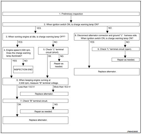
DETAILED FLOW
1.PRELIMINARY INSPECTION
Perform the preliminary inspection. Refer to CHG-17, "Inspection Procedure".
>> GO TO 2.
2.INSPECTION WITH CHARGE WARNING LAMP (IGNITION SWITCH IS ON)
Turn the ignition switch ON.
Does the charge warning lamp illuminate? YES >> GO TO 3.
NO >> GO TO 8.
3.INSPECTION WITH CHARGE WARNING LAMP (IDLING)
Start the engine and run it at idle.
Does the charge warning lamp turn OFF? YES >> GO TO 4.
NO >> GO TO 5.
4.INSPECTION WITH CHARGE WARNING LAMP (ENGINE AT 2,500 RPM)
Increase and maintain the engine speed at 2,500 rpm.
Does the charge warning lamp illuminate? YES >> GO TO 6.
NO >> INSPECTION END
5.“L” TERMINAL CIRCUIT (SHORT) INSPECTION
Check “L” terminal circuit (short). Refer to CHG-23, "Diagnosis Procedure".
Is the inspection result normal? YES >> GO TO 6.
NO >> Repair as needed.
6.MEASURE “B” TERMINAL VOLTAGE
Engine start. When keeping engine running at 2,500 rpm, measure “B” terminal voltage.
What voltage does the measurement result show? Less than 13.0 V>>GO TO 7.
More than 16.0 V>>Replace alternator.
7.“B” TERMINAL CIRCUIT INSPECTION
Check “B” terminal circuit. Refer to CHG-20, "Diagnosis Procedure".
Is the inspection result normal? YES >> Replace alternator.
NO >> Repair as needed.
8.INSPECTION WITH CHARGE WARNING LAMP (IGNITION SWITCH IS ON)
1. Disconnect alternator connector and ground “L” harness side.
2. Turn the ignition switch ON.
Does the charge warning lamp illuminate? YES >> Replace alternator.
NO >> GO TO 9.
9.CHECK “L” TERMINAL CIRCUIT (OPEN)
Check “L” terminal circuit (open). Refer to CHG-21, "Diagnosis Procedure".
>> Repair as needed.
 Basic inspection
...
 Charging system preliminary inspection
Inspection Procedure
1.CHECK BATTERY TERMINALS CONNECTION
Check if battery terminals are clean and tight.
Is the inspection result normal?
YES >> GO TO 2.
NO >> Repair battery ter ...
Other materials:
Component parts
Manual air conditioning system : Component Part Location
1. BCM
• With Intelligent Key: Refer to BCS-
6, "BODY CONTROL SYSTEM :
Component Parts Location".
• Without Intelligent Key: Refer to
BCS-161, "Removal and Installation".
2. Magnet clutch
3. Refrigerant pressure ...
Rear seat (2WD)
Exploded View
1. Headrest
2. Headrest holder (locked)
3. Headrest holder (free)
4. Seatback trim RH
5. Seatback pad RH
6. Seat lock cover RH
7. Seatback lock knob
8. Seatback lock knob finisher
9. Seatback lock assembly RH
10. Striker RH
11. Lock washer
12. Side hinge
13. Bush ...
Precaution for Brake System
WARNING:
Clean any dust from the front brake and rear brake using a vacuum dust
collector. Never blow by compressed
air.
• Brake fluid use refer to MA-13, "Fluids and Lubricants".
• Never reuse drained brake fluid.
• Never spill or splash brake fluid on painted surfaces. Brake fluid ...
