Nissan Juke Service and Repair Manual : Diagnosis and repair work flow
Work Flow
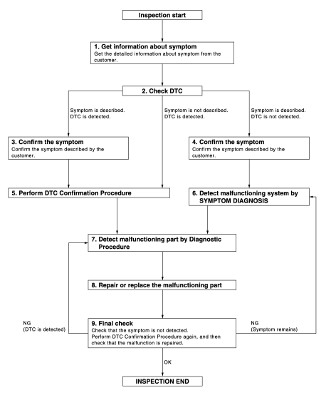
OVERALL SEQUENCE
DETAILED FLOW
1.GET INFORMATION ABOUT SYMPTOM
Get the detailed information from the customer about the symptom (the condition and the environment when the incident/malfunction occurred).
>> GO TO 2.
2.CHECK DTC
1. Check DTC for “ENGINE” and “BCM” using CONSULT-III.
2. Perform the following procedure if DTC is displayed.
- Erase DTC.
- Study the relationship between the cause detected by DTC and the symptom described by the customer.
3. Check related service bulletins for information.
Is any symptom described and any DTC detected? Symptom is described, DTC is displayed>>GO TO 3.
Symptom is described, DTC is not displayed>>GO TO 4.
Symptom is not described, DTC is displayed>>GO TO 5.
3.CONFIRM THE SYMPTOM
Confirm the symptom described by the customer.
Connect CONSULT-III to the vehicle and check self diagnosis results in real time.
Verify relation between the symptom and the condition when the symptom is detected.
>> GO TO 5.
4.CONFIRM THE SYMPTOM
Confirm the symptom described by the customer.
Connect CONSULT-III to the vehicle and check self diagnosis results in real time.
Verify relation between the symptom and the condition when the symptom is detected.
>> GO TO 6.
5.PERFORM DTC CONFIRMATION PROCEDURE
Perform DTC CONFIRMATION PROCEDURE for the displayed DTC, and then check that DTC is detected again.
If two or more DTCs are detected, refer to BCS-140, "DTC Inspection Priority Chart" (BCM) and then determine the trouble diagnosis order.
Is DTC detected? YES >> GO TO 7.
NO >> Refer to GI-42, "Intermittent Incident".
6.DETECT MALFUNCTIONING SYSTEM BY SYMPTOM DIAGNOSIS
Detect malfunctioning system according to SYMPTOM DIAGNOSIS based on the confirmed symptom in step 4, and determine the trouble diagnosis order based on possible causes and symptom.
>> GO TO 7.
7.DETECT MALFUNCTIONING PART BY DIAGNOSTIC PROCEDURE
Inspect according to Diagnostic Procedure of the system.
>> GO TO 8.
8.REPAIR OR REPLACE THE MALFUNCTIONING PART
1. Repair or replace the malfunctioning part.
2. Reconnect parts or connectors disconnected during Diagnostic Procedure again after repair and replacement.
3. Check DTC. If DTC is displayed, erase it.
>> GO TO 9.
9.FINAL CHECK
When DTC was detected in step 2, perform DTC CONFIRMATION PROCEDURE again, and then check that the malfunctions have been fully repaired.
When symptom was described by the customer, refer to the confirmed symptom in step 3 or 4, and check that the symptom is not detected.
Does the symptom reappear? YES (DTC is detected)>>GO TO 7.
YES (Symptom remains)>>GO TO 6.
NO >> INSPECTION END
 Basic inspection
...
 Additional service when replacing control unit
ECM
ECM : Description
Performing the following procedure can automatically activate recommunication
of ECM and BCM, but only
when the ECM is replaced with a new one*.
*: New one means a virgin ...
Other materials:
Map lamp
Exploded View
1. Map lamp bulb housing
2. Bulb
3. Lens
: Pawl
Removal and Installation
CAUTION:
Disconnect the battery negative terminal or the fuse.
REMOVAL
1. Remove the lens (1).
• Insert a remover tool (A) into the gap between the lens.
• Disengage the lens fixing pawls, and then ...
Combination meter
Reference Value
VALUES ON THE DIAGNOSIS TOOL
NOTE:
Some items are not available according to vehicle specification.
TERMINAL LAYOU
PHYSICAL VALUES
Fail-Safe
FAIL-SAFE
The combination meter activates the fail-safe control if CAN communication
with each unit is malfunctio ...
Sensor rotor
Front sensor rotor : Removal and Installation
REMOVAL
Replace wheel hub as an assembly when replacing because sensor rotor cannot
be disassembled. Refer to
FAX-43, "Removal and Installation".
INSTALLATION
Replace wheel hub as an assembly when replacing because sensor rotor cannot ...
