Nissan Juke Service and Repair Manual : Diagnosis and repair work flow
Work Flow
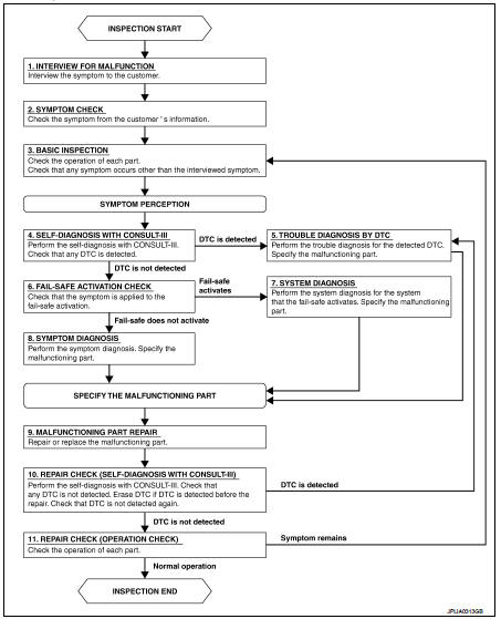
OVERALL SEQUENCE
DETAILED FLOW
1.INTERVIEW FOR MALFUNCTION
Interview the symptom to the customer.
>> GO TO 2.
2.SYMPTOM CHECK
Check the symptom from the customer's information.
>> GO TO 3.
3.BASIC INSPECTION Check the operation of each part. Check that any symptom occurs other than the interviewed symptom.
>> GO TO 4.
4.SELF-DIAGNOSIS WITH CONSULT-III
Perform the self-diagnosis with CONSULT-III. Check that any DTC is detected.
Is any DTC detected? YES >> GO TO 5.
NO >> GO TO 6.
5.TROUBLE DIAGNOSIS BY DTC
Perform the trouble diagnosis for the detected DTC. Specify the malfunctioning part.
>> GO TO 9.
6.FAIL-SAFE ACTIVATION CHECK
Check that the symptom is applied to the fail-safe activation.
Does the fail-safe activate? YES >> GO TO 7.
NO >> GO TO 8.
7.SYSTEM DIAGNOSIS
Perform the system diagnosis for the system that the fail-safe activates. Specify the malfunctioning part.
>> GO TO 9.
8.SYMPTOM DIAGNOSIS
Perform the symptom diagnosis. Specify the malfunctioning part.
>> GO TO 9.
9.MALFUNCTION PART REPAIR
Repair or replace the malfunctioning part.
>> GO TO 10.
10.REPAIR CHECK (SELF-DIAGNOSIS WITH CONSULT-III)
Perform the self-diagnosis with CONSULT-III. Check that any DTC is not detected. Erase DTC if DTC is detected before the repair. Check that DTC is not detected again.
Is any DTC detected? YES >> GO TO 5.
NO >> GO TO 11.
11.REPAIR CHECK (OPERATION CHECK)
Check the operation of each part.
Does it operate normally? YES >> INSPECTION END
NO >> GO TO 3.
 Basic inspection
...
 Operation inspection
Work Procedure
The purpose of the operational check is to check that the individual system
operates normally.
Check condition : Engine running at normal operating temperature.
1.CHECK MEMORY FUNC ...
Other materials:
System
Warning chime system
WARNING CHIME SYSTEM : System Diagram
WARNING CHIME SYSTEM : System Description
COMBINATION METER
The combination meter sounds the alarm buzzer installed in the combination
meter when receiving the buzzer
output signal transmitted from each unit.
BCM
BCM receives si ...
Basic inspection
Inspection and adjustment
Additional service when replacing control unit (BCM)
ADDITIONAL SERVICE WHEN REPLACING CONTROL UNIT (BCM) : Description
BEFORE REPLACEMENT
When replacing BCM, save or print current vehicle specification with
CONSULT-III configuration before
replacement.
NOTE:
If ...
Cooling fan
Exploded View
1. Fan motor
2. Fan shroud
3. Cooling fan
A. Apply on fan motor shaft
: N·m (kg-m, in-lb)
: Apply genuine high strength thread
locking sealant or equivalent.
Removal and Installation
REMOVAL
1. Drain engine coolant. Refer to CO-11, "Draining".
CAUTION:
• Pe ...
