Nissan Juke Service and Repair Manual : Cooling fan control
Cooling fan control : System Diagram
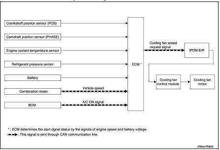
Cooling fan control : System Description
INPUT/OUTPUT SIGNAL CHART
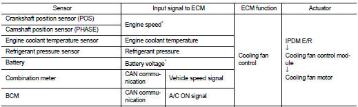
*: The ECM determines the start signal status by the signals of engine speed and battery voltage.
SYSTEM DESCRIPTION
ECM controls cooling fan speed corresponding to vehicle speed, engine coolant temperature, A/C ON signal and refrigerant pressure.
Cooling fan control signal is sent to IPDM E/R from ECM by CAN communication line. Then, IPDM E/R sends ON/OFF pulse duty signal to cooling fan control module. Corresponding to this ON/OFF pulse duty signal, cooling fan control module gives cooling fan motor operating voltage to cooling fan motors. Cooling fan speed is controlled by duty cycle of cooling fan motor operating voltage sent from cooling fan control module.
 Air conditioning cut control
Air conditioning cut control : System Diagram
Air conditioning cut control : System Description
INPUT/OUTPUT SIGNAL CHART
*: ECM determines the start signal status by the signals of engine spe ...
 Starter motor drive control
Starter motor drive control : System Diagram
Starter motor drive control : System
DescriptionINPUT/OUTPUT SIGNAL CHART
INPUT/OUTPUT SIGNAL CHART
*: With Intelligent Key system
SYSTEM DESCRIPT ...
Other materials:
P2100, P2103 throttle control motor relay
DTC Logic
DTC DETECTION LOGIC
DTC CONFIRMATION PROCEDURE
1.PRECONDITIONING
If DTC Confirmation Procedure has been previously conducted, always turn
ignition switch OFF and wait at
least 10 seconds before conducting the next test.
TESTING CONDITION:
Before performing the following proced ...
P0848 transmission fluid pressure SEN/SW B
DTC Logic
DTC DETECTION LOGIC
DTC CONFIRMATION PROCEDURE
1.PREPARATION BEFORE WORK
If another "DTC CONFIRMATION PROCEDURE" occurs just before, the ignition
switch OFF and wait for at
least 10 seconds, then perform the next test.
>> GO TO 2.
2.CHECK DTC DETECTION
With ...
Input shaft and gear
Exploded View
1. Input shaft front bearing
2. Input shaft
3. Snap ring
4. Input shaft rear bearing
5. Adapter plate
6. Bushing
7. 5th input gear
8. 5th-reverse baulk ring
9. Synchronizer lever
10. 5th-reverse synchronizer hub
11. 5th-reverse coupling sleeve
12. Retaining pin
1 ...
