Nissan Juke Service and Repair Manual : Cooling fan
Exploded View
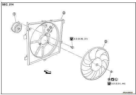
1. Fan motorCooling fan
2. Fan shroud
3. Cooling fan
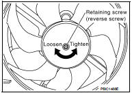
A. Reverse screw
 : Apply thread locking sealant.
 : Vehicle front
 : N·m (kg-m, in-lb)
Removal and Installation
REMOVAL
1. Drain engine coolant. Refer to CO-62, "Draining".
2. Disconnect radiator hose (lower) clip.
3. Remove battery. Refer to PG-124, "Exploded View" 4. Remove air duct (inlet). Refer to EM-280, "Exploded View".
5. Remove fusible link and relay box bracket, and put fusible link and relay box aside.
6. Remove reservoir tank.
7. Disconnect fan motor connector and boost pressure control valve harness connector, and put the connectors aside.
8. Remove boost pressure control valve assembly. Refer to EC-825, "TURBOCHARGER BOOST CONTROL : Vacuum Hose Drawing".
9. Remove radiator upper hose. Refer to CO-66, "Exploded View".
10. Remove radiator fan and shroud assembly.
11. Remove radiator fan reverse screw.
12. Remove fan motor from fan shroud.
INSTALLATION
Install in the reverse order of removal.
 Radiator
Exploded View
1. Reservoir tank cap
2. Reservoir tank
3. Clamp
4. Reservoir tank hose
5. Mounting rubber (upper)
6. Reservoir tank hose
7. Radiator
8. Mounting rubber (lower)
9. Drain ...
 Water pump
Exploded View
1. Water pump
2. Gasket
3. Cylinder block
Removal and Installation
WARNING:
Never remove the radiator cap when the engine is hot. Serious burns could occur
from high pressure ...
Other materials:
Precaution for Supplemental Restraint System (SRS) "AIR BAG" and "SEAT BELT
PRE-TENSIONER"
The Supplemental Restraint System such as “AIR BAG” and “SEAT BELT PRE-TENSIONER”,
used along
with a front seat belt, helps to reduce the risk or severity of injury to the
driver and front passenger for certain
types of collision. Information necessary to service the system safely is
include ...
P012B TC boost sensor
DTC Logic
DTC DETECTION LOGIC
Diagnosis Procedure
1.CHECK GROUND CONNECTIONS
1. Turn ignition switch OFF.
2. Check ground connection E38. Refer to Ground inspection in GI-44, "Circuit
Inspection".
Is the inspection result normal?
YES >> GO TO 2.
NO >> Repair or ...
P0833 CPP switch
DTC Logic
DTC DETECTION LOGIC
Diagnosis Procedure
1.CHECK CLUTCH PEDAL POSITION SWITCH GROUND CIRCUIT FOR OPEN AND SHORT
1. Turn ignition switch OFF.
2. Disconnect clutch pedal position switch harness connector.
3. Check the continuity between clutch pedal position switch harness connector
...
