Nissan Juke Service and Repair Manual : Cooling fan
Diagnosis Procedure
1.CHECK GROUND CONNECTION
1. Turn ignition switch OFF.
2. Check ground connection E38. Refer to Ground Inspection in GI-44, "Circuit Inspection".
Is the inspection result normal? YES >> GO TO 2.
NO >> Repair or replace ground connection.
2.CHECK COOLING FAN MOTOR CIRCUIT
1. Disconnect cooling fan motor harness connector.
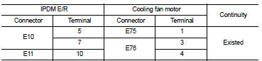
2. Check the continuity between IPDM E/R harness connector and cooling fan motor harness connector.
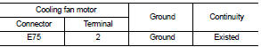
3. Check the continuity between cooling fan motor harness connector and ground.
4. Also check harness for short to ground and short to power.
YES or NO YES >> GO TO 4.
NO >> GO TO 3.
3.DETECT MALFUNCTIONING PART
Check the following.
• Harness for open or short between cooling fan motor and IPDM E/R • Harness for open or short between cooling fan motor and ground
>> Repair open circuit or short to ground or short to power in harness or connectors.
4.CHECK COOLING FAN MOTOR
Refer to EC-1015, "Component Inspection".
YES or NO YES >> GO TO 5.
NO >> Replace cooling fan motor.
5.CHECK INTERMITTENT INCIDENT
Perform GI-42, "Intermittent Incident".
YES or NO YES >> Replace IPDM E/R. Refer to PCS-34, "Exploded View" (WITH I-KEY) or PCS-63, "Exploded View" (WITHOUT I-KEY).
NO >> Repair or replace harness or connector.
Component Inspection
1.CHECK COOLING FAN MOTOR
1. Turn ignition switch OFF.
2. Disconnect cooling fan motor harness connector E75 and E76.
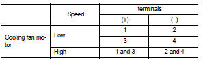
3. Supply cooling fan motor terminals with battery voltage and check operation.
Is the inspection result normal? YES >> INSPECTION END
NO >> Replace cooling fan motor.
 CAN communication circuit
Description
CAN (Controller Area Network) is a serial communication line for real time
application. It is an on-vehicle multiplex
communication line with high data communication speed and excellen ...
 Information display (ASCD)
Component Function Check
1.CHECK INFORMATION DISPLAY
1. Start engine.
2. Press ASCD MAIN switch.
3. Drive the vehicle at more than 30 km/h (20 MPH)
CAUTION:
Always drive vehicle at a safe speed. ...
Other materials:
Door does not lock/unlock with intelligent key
Diagnosis Procedure
1.CHECK DTC WITH BCM AND TCM
Check that DTC is not detected with BCM and TCM.
Is the inspection result normal?
YES >> GO TO 2.
NO-1 >> Refer to BCS-67, "DTC Index". (BCM)
NO-2 >> Refer to TM-171, "DTC Index" (RE0F10B models) or TM-3 ...
P0130 A/F sensor 1
DTC Logic
DTC DETECTION LOGIC
To judge the malfunction, the diagnosis checks that the A/F signal computed
by ECM from the A/F sensor 1
signal fluctuates according to fuel feedback control.
DTC CONFIRMATION PROCEDURE
1.PRECONDITIONING
If DTC Confirmation Procedure has been previously conduc ...
P0560 battery voltage
DTC Logic
DTC DETECTION LOGIC
NOTE:
When IPDM E/R DTC is indicated with DTC P0560, IPDM E/R DTC must be checked
first.
Diagnosis Procedure
1.CHECK BATTERY VOLTAGE
1. Turn ignition switch ON.
2. Check battery voltage.
Voltage: Above 11 V
Is the inspection result normal?
YES >> GO ...
