Nissan Juke Service and Repair Manual : Connector Symbols
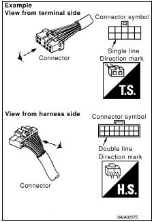
Most of connector symbols in wiring diagrams are shown from the terminal side.
• Connector symbols shown from the terminal side are enclosed by a single line and followed by the direction mark.
• Connector symbols shown from the harness side are enclosed by a double line and followed by the direction mark.
• Certain systems and components, especially those related to OBD, may use a new style slide-locking type harness connector.
For description and how to disconnect, refer to PG section, “Description”, “HARNESS CONNECTOR”.
• Male and female terminals Connector guides for male terminals are shown in black and female terminals in white in wiring diagrams.

 Sample/Wiring Diagram -Example-
Each section includes wiring diagrams.
Description
SWITCH POSITIONS
Switches are shown in wiring diagrams as if the vehicle is in the “normal”
condition.
A vehicle is in the “normal” con ...
Other materials:
B1135 side air bag module LH
DTC Logic
DTC DETECTION LOGIC
DTC CONFIRMATION PROCEDURE
1.CHECK SELF-DIAG RESULT
With CONSULT-III
1. Turn ignition switch ON.
2. Perform “Self Diagnostic Result” mode of “AIR BAG” using CONSULT-III.
Without CONSULT-III
1. Turn ignition switch ON.
2. Check the air bag warning lamp statu ...
Both side front fog lamps are not turned on
Description
The front fog lamps are not turned ON in any condition.
Diagnosis Procedure
1.CHECK FUSE
Check that the following fuse is fusing.
Is the inspection result normal?
YES >> GO TO 2.
NO >> Repair the applicable circuit. And then replace the fuse.
2.COMBINATION SWITC ...
P2263 TC system
DTC Logic
DTC DETECTION LOGIC
Diagnosis Procedure
1.CHECK VACUUM HOSES AND VACUUM GALLERY
1. Turn ignition switch OFF.
2. Check vacuum hoses and vacuum gallery for clogging, cracks
or improper connection. Refer to EC-825, "TURBOCHARGER
BOOST CONTROL : Vacuum Hose Drawing".
Is t ...
