Nissan Juke Service and Repair Manual : Condenser
Exploded View
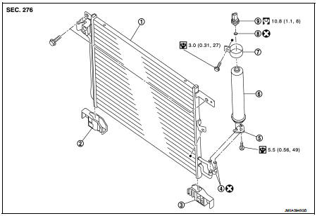
1. Condenser
2. Condenser lower bracket RH
3. Condenser lower bracket LH
4. O-ring
5. Liquid tank braket
6. Liquid tank
7. Braket
8. O-ring
9. Refrigerant pressure sensor
 : Do not reuse
 : N·m (kg-m, in-lb)
 : N·m (kg-m, ft-lb)
Condenser : Removal and Installation
CAUTION:
Perform lubricant return operation before each refrigeration system disassembly.
However, if a large
amount of refrigerant or lubricant is detected, never perform lubricant return
operation. Refer to HA-
78, "Perform Lubricant Return Operation".
REMOVAL
1. Use a refrigerant collecting equipment (for HFC-134a) to discharge the refrigerant. Refer to HA-76, "Recycle Refrigerant".
2. Remove front bumper fascia assembly. Refer to EXT-13, "Removal and Installation".
3. Remove air guide (LH). Refer to DLK-149, "MR16DDT : Exploded View".
4. Disconnect refrigerant pressure sensor harness connector.
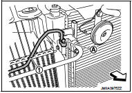
5. Remove mounting bolt (A), and then disconnect high-pressure pipe (1) from condenser.
CAUTION:
Cap or wrap the joint of the A/C piping and condenser with
suitable material such as vinyl tape to avoid the entry of air.
 : Vehicle front
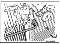
6. Remove mounting bolt (A), and then disconnect high-pressure flexible hose from condenser.
CAUTION:
Cap or wrap the joint of the A/C piping and condenser with
suitable material such as vinyl tape to avoid the entry of air.
 : Vehicle front
7. Remove mounting bolts, and then remove condenser from the vehicle.
CAUTION:
Be careful not to damage core surface of condenser.
INSTALLATION
Note the following items, and then install in the reverse order of removal.
CAUTION:
• Replace O-rings with new ones. Then apply compressor oil to them when
installing.
• Perform lubricant adjusting procedure before installing new condenser. Refer to HA-79, "Lubricant Adjusting Procedure for Compressor Replacement".
• Check for leakages when recharging refrigerant. Refer to HA-74, "Leak Test".
Liquid tank : Removal and Installation
CAUTION:
Perform lubricant return operation before each refrigeration system disassembly.
However, if a large
amount of refrigerant or lubricant is detected, never perform lubricant return
operation. Refer to HA-
78, "Perform Lubricant Return Operation".
REMOVAL
1. Use a refrigerant collecting equipment (for HFC-134a) to discharge the refrigerant. Refer to HA-76, "Recycle Refrigerant".
2. Remove front bumper fascia assembly. Refer to EXT-13, "Removal and Installation".
3. Remove air guide (LH). Refer to DLK-149, "MR16DDT : Exploded View".
4. Clean liquid tank and its surrounding area, and then remove dust and rust from liquid tank.
5. Diconnect refrigerant pressure sensor harness connector.
6. Remove mounting bolts, and then remove liquid tank from condenser.
CAUTION:
Cap or wrap the joint of the A/C piping and liquid tank with suitable material
such as vinyl tape to
avoid the entry of air.
INSTALLATION
Note the following items, and install in the reverse order of removal.
CAUTION
:
• Replace O-rings of the A/C piping with new ones. Then apply compressor oil to
them when installing.
• Perform lubricant adjusting procedure before installing new liquid tank. Refer to HA-79, "Lubricant Adjusting Procedure for Compressor Replacement".
• Check for leakages when recharging refrigerant. Refer to HA-74, "Leak Test".
Refrigerant pressure sensor : Removal and Installation
CAUTION:
Perform lubricant return operation before each refrigeration system disassembly.
However, if a large
amount of refrigerant or lubricant is detected, never perform lubricant return
operation. Refer to HA-
78, "Perform Lubricant Return Operation".
REMOVAL
1. Use a refrigerant collecting equipment (for HFC-134a) to discharge the refrigerant. Refer to HA-76, "Recycle Refrigerant".
2. Remove front bumper fascia. Refer to EXT-13, "Removal and Installation".
3. Clean refrigerant pressure sensor and its surrounding area, and then remove dust and rust from refrigerant pressure sensor.
4. Disconnect refrigerant pressure sensor connector.
5. Use a adjustable wrench or other tool to hold the refrigerant pressure sensor mounting block, and then remove the refrigerant pressure sensor from condenser.
CAUTION:
• Be careful not to damage core surface of condenser.
• Cap or wrap the joint of the condenser and liquid tank with suitable material such as vinyl tape to avoid the entry of air.
INSTALLATION
Note the following items, and then install in the reverse order of removal.
CAUTION:
• Replace O-ring with new one. Then apply compressor oil to them when
installing.
• Check for leakages when recharging refrigerant. Refer to HA-74, "Leak Test".
 Cooler pipe and hose
Exploded View
1. A/C unit assembly
2. O-ring
3. High-pressure pipe
4. O-ring
5. Low-pressure flexible hose
6. High-pressure flexible hose
7. O-ring
8. Condenser
9. Compressor
: Do not ...
 A/C unit assembly
Exploded View (Automatic Air Conditioning)
REMOVAL
LHD models (4WD)
1. A/C unit assembly
2. Drain hose
3. Steering member
4. Instrument stay
: Clip
: N·m (kg-m, ft-lb)
DISASSEMBLY
LHD mo ...
Other materials:
Component parts
Manual air conditioning system : Component Part Location
1. BCM
• With Intelligent Key: Refer to BCS-
6, "BODY CONTROL SYSTEM :
Component Parts Location".
• Without Intelligent Key: Refer to
BCS-161, "Removal and Installation".
2. Magnet clutch
3. Refrigerant pressure ...
C1144 incomplete steering angle sensor adjustment
DTC Logic
DTC DETECTION LOGIC
DTC CONFIRMATION PROCEDURE
1.PRECONDITIONING
If “DTC CONFIRMATION PROCEDURE” has been previously conducted, always turn
ignition switch OFF and
wait at least 10 seconds before conducting the next test.
>> GO TO 2.
2.CHECK DTC DETECTION
With CONSULT ...
Manual Transmission (MT)
WARNING
• Do not downshift abruptly on slippery roads. This may cause a loss
of control.
• Do not over-rev the engine when shifting to a lower gear. This may cause a loss
of control or engine damage.
• When the high fluid temperature protection mode or fail-safe operation occurs,
vehi ...
