Nissan Juke Service and Repair Manual : Compressor dose dot operate
Description
SYMPTOM
Compressor dose not operate.
Diagnosis Procedure
NOTE
:
• Perform self-diagnosis with CONSULT-III before performing symptom diagnosis.
If any malfunction result or
DTC is detected, perform the corresponding diagnosis.
• Check that refrigerant is enclosed in cooler cycle normally. If the refrigerant amount is shortage from proper amount, perform the inspection of refrigerant leakage 1.CHECK A/C INDICATOR
1. Turn ignition switch ON.
2. Operate blower motor.
3. Check that A/C indicator is turned ON/OFF when operating A/C switch.
Is the inspection result normal? YES >> GO TO 2.
NO >> GO TO 5.
2.CHECK MAGNET CLUTCH OPERATION
Check magnet clutch. Refer to HAC-293, "Component Function Check".
Does it operate normally? YES >> GO TO 3.
NO >> Repair or replace malfunctioning parts.
3.CHECK REFRIGERANT PRESSURE SENSOR
Check refrigerant pressure sensor. Refer to the following.
• HR16DE: Refer to EC-790, "Component Function Check".
• MR16DDT: Refer to EC-423, "Component Function Check".
• K9K: Refer to EC-960, "DTC Logic".
Is the inspection result normal? YES >> GO TO 4.
NO >> Repair or replace malfunctioning parts.
4.CHECK BCM OUTPUT SIGNAL
 With CONSULT-III
1. Select “DATA MONITOR” mode of “ECM” using CONSULT-III.
2. Select “AIR COND SIG” and “HEATER FAN SW”, and check status under the following conditions.
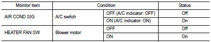
Is the inspection result normal? YES >> Replace IPDM E/R. Refer to PCS-34, "Removal and Installation" (with Intelligent Key) or PCS-63, "Removal and Installation" (without Intelligent Key).
NO >> Replace BCM. Refer to BCS-93, "Removal and Installation" (with Intelligent Key) or BCS-161, "Removal and Installation" (without Intelligent Key).
5.CHECK A/C SWITCH
Check A/C switch. Refer to HAC-281, "Component Function Check".
Is the inspection result normal? YES >> GO TO 6.
NO >> Repair or replace the malfunctioning parts.
6.CHECK BLOWER FAN ON SIGNAL
Check blower fan ON signal. Refer to HAC-283, "Component Function Check".
Is the inspection result normal? YES >> GO TO 7.
NO >> Repair or replace the malfunctioning parts 7.CHECK THERMO CONTROL AMP.
Check thermo control amp. Refer to HAC-285, "Component Function Check".
Is the inspection result normal? YES >> Replace BCM. Refer to BCS-93, "Removal and Installation" (with Intelligent Key) or BCS-161, "Removal and Installation" (without Intelligent Key).
NO >> Repair or replace the malfunctioning parts
 Insufficient heating
Description
Symptom
• Insufficient heating
• No warm air comes out. (Air flow volume is normal.)
Diagnosis Procedure
NOTE:
Perform self-diagnosis with CONSULT-III before performing symptom diagn ...

Other materials:
Environmental factors influence the rate of corrosion
Moisture
Accumulation of sand, dirt and water on the vehicle body underside can accelerate
corrosion.
Wet floor coverings will not dry completely inside the vehicle, and should be
removed for drying to avoid floor panel corrosion.
Relative humidity
Corrosion will be accelerated in areas of h ...
U1010 control unit (can)
Description
CAN (Controller Area Network) is a serial communication line for real time
application. It is an on-vehicle multiplex
communication line with high data communication speed and excellent error
detection ability. Many electronic
control units are equipped onto a vehicle, and each co ...
Cooling fan control
Cooling fan control : System Diagram
Cooling fan control : System Description
INPUT/OUTPUT SIGNAL CHART
*: The ECM determines the start signal status by the signals of engine speed
and battery voltage.
SYSTEM DESCRIPTION
ECM controls cooling fan speed corresponding to vehicle speed, eng ...
