Nissan Juke Service and Repair Manual : Component parts
Body control system
BODY CONTROL SYSTEM : Component Parts Location
RHD MODELS
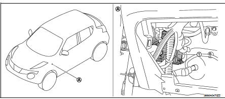
1. BCM
A. Behind of glove box (Left side)
LHD MODELS
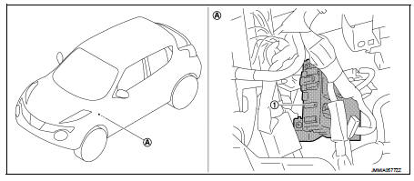
1. BCM
A. Behind of instrument lower panel LH (Left side)
Power consumption control system
POWER CONSUMPTION CONTROL SYSTEM : Component Parts Location
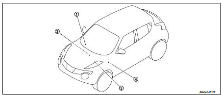
1. Combination meter 2. Multi display unit Refer to AV-96, "Component Parts Location".
3. IPDM E/R Refer to PCS-5, "Component Parts Location".
4. BCM Refer to BCS-6, "BODY CONTROL SYSTEM : Component Parts Location".

 System
Body control system
BODY CONTROL SYSTEM : System Description
OUTLINE
• BCM (Body Control Module) controls the various electrical components. It
inputs the information required to
the control fro ...
Other materials:
Front oil seal
Exploded View
1. Rear final drive assembly
2. Front oil seal
3. Companion flange
4. Companion flange lock nut
A. Oil seal lip
: Vehicle front
: N·m (kg-m, ft-lb)
: Never reuse parts
: Apply multi purpose grease
: Apply gear oil.
Removal and Installation
REMOVAL
CAUTION:
Verify iden ...
Diagnosis system (EPS control unit)
Consult-III Function
FUNCTION
CONSULT-III can display each diagnostic item using the diagnostic test modes
shown following.
*: The following diagnosis information is erased by erasing.
• DTC
• Freeze frame data (FFD)
ECU IDENTIFICATION
Displays the part number stored in the control unit.
...
Wiring diagram
NISSAN DYNAMIC CONTROL SYSTEM
Wiring Diagram
For connector terminal arrangements, harness layouts, and alphabets in a
(option abbreviation; if not
described in wiring diagram), refer to GI-12, "Connector Information/Explanation
of Option Abbreviation".
...
