Nissan Juke Service and Repair Manual : Component parts
Component Parts Location
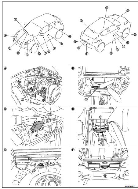
1. Combination meter
2. Intelligent Key warning buzzer
3. Push-button ignition switch
4. Inside key antenna (instrument center)
5. TCM
Refer to TM-133, "CVT CONTROL
SYSTEM : TCM" (RE0F10B models)
or TM-316, "CVT CONTROL SYSTEM
: TCM" (RE0F11A models)
6. Remote keyless entry receiver
7. BCM
Refer to BCS-6, "BODY CONTROL
SYSTEM : Component Parts Location"
8. Power window switch (passenger
side) (door lock and unlock switch)
9. Outside key antenna (passenger side)
10. Front door request switch (passenger
side)
11. Inside key antenna (console)
12. Inside key antenna (luggage room)
13. Back door request switch
14. Back door lock assembly
15. Outside antenna (rear bumper)
16. Front door lock assembly (driver side)
17. Front door switch (driver side)
18. Front door request switch (driver side)
19. Outside key antenna (driver side)
20. Power window main switch (door lock
and unlock switch)
21. Door lock status indicator
22. Air bag diagnosis sensor unit
Refer to SRC-7, "Component Parts Location"
A. View with front bumper removed B. View with multi display unit removed C.
View with instrument panel assembly
removed
D. View with center console assembly removed
E. View with luggage room finisher removed
F. View with rear bumper removed
Component Description
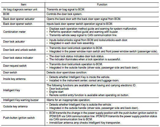
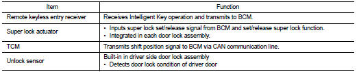

 System (power door lock system)
System Diagram
System Description
DOOR LOCK FUNCTION
Door Lock and Unlock Switch
• The door lock and unlock switch (driver side) is build into power window main
switch.
• The door lock and un ...
Other materials:
Precaution Necessary for Steering Wheel Rotation after Battery Disconnect
NOTE:
• Before removing and installing any control units, first turn the ignition
switch to the LOCK position, then disconnect
both battery cables.
• After finishing work, confirm that all control unit connectors are connected
properly, then re-connect both
battery cables.
• Always use CONS ...
P0530 refrigerant pressure sensor
DTC Logic
DTC DETECTION LOGIC
Diagnosis Procedure
1.CHECK GROUND CONNECTIONS
1. Turn ignition switch OFF.
2. Check ground connection E38. Refer to Ground inspection in GI-44, "Circuit
Inspection".
Is the inspection result normal?
YES >> GO TO 2.
NO >> Repair or ...
Power door lock system
System Diagram
System Description
DOOR LOCK FUNCTION
• The door lock and unlock switch (driver side) is build into power window
main switch.
• Interlocked with the locking operation of door lock and unlock switch, door
lock actuators of all doors are
locked.
• Interlocked with the unlock ...
