Nissan Juke Service and Repair Manual : Component parts
Component Parts Location
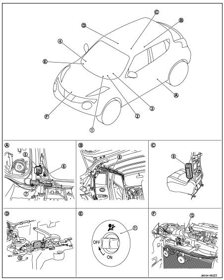
1. Combination meter Refer to MWI-4, "METER SYSTEM : Component Parts Location".
2. Combination switch (spiral cable)
3. Driver air bag module
Crash zone sensor
4. Passenger air bag module
5. Seat belt pre-tensioner LH
6. Satellite sensor LH
7. Lap pre-tensioner LH
8. Curtain air bag module LH
9. Side air bag module LH
10. Air bag diagnosis sensor unit
11. Air bag cutoff switch
12. Crash zone sensor
A. Behind rear side finisher
B. View with headlining assembly removed
C. View with seatback pad removed
D. View with center console assembly
removed
E. View with glove box assembly open
F. Radiator core support assembly
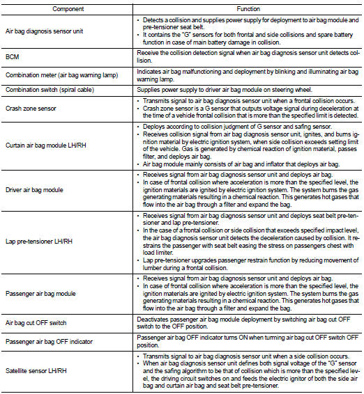
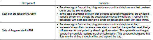
Component Description

 System
System Diagram
System Description
Supplemental Restraint System (SRS) activates air bag module and seat belt
pre-tensioner when it detects a
frontal collision or a side collision that is more t ...
Other materials:
Wiring diagram
POWER WINDOW SYSTEM
LHD
LHD : Wiring Diagram
For connector terminal arrangements, harness layouts, and alphabets in a
(option abbreviation; if not
described in wiring diagram), refer to GI-12, "Connector Information/Explanation
of Option Abbreviation".
RHD
RHD : Wiring Diagram
...
Intelligent key warning buzzer
Component Function Check
1.CHECK FUNCTION
1. Select “INTELLIGENT KEY” of “BCM” using CONSULT-III.
2. Select “OUTSIDE BUZZER” in “ACTIVE TEST” mode.
3. Check that the function operates normally according to the following
conditions.
Is the inspection result normal?
YES >> Intelligent ...
Door motor
Diagnosis Procedure
NOTE:
If all of door motor DTCs are detected, check this circuit.
1.CHECK DOOR MOTOR POWER SUPPLY
1. Turn ignition switch ON.
2. Check voltage between intake door motor harness connector and ground.
Is the inspection result normal?
YES >> GO TO 2.
NO >> ...
