Nissan Juke Service and Repair Manual : Component parts
Component Parts Location
LHD models
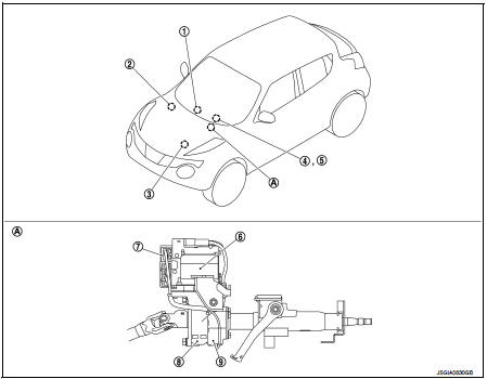
1. Multi display unit* Refer to DMS-3, "Component Parts Location".
2. ABS actuator and electric unit (control unit) Refer to BRC-9, "Component Parts Location" (without ESP), BRC-97, "Component Parts Location" (with ESP).
3. ECM Refer to EC-25, "ENGINE CONTROL SYSTEM : Component Parts Location" (MR16DDT), EC-455, "ENGINE CONTROL SYSTEM : Component Parts Location" (HR16DE), EC-813, "Component Parts Location" (K9K).
4. Combination meter Refer to MWI-4, "METER SYSTEM : Component Parts Location".
5. EPS warning lamp
(In combination meter)
6. EPS motor
7. EPS control unit
8. Reduction gear
9. Torque sensor
A. Steering column assembly
*: Models with Nissan Dynamic Control Syste
RHD models
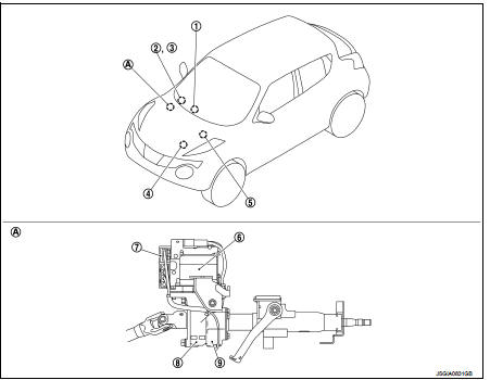
1. Multi display unit* Refer to DMS-3, "Component Parts Location".
2. Combination meter Refer to MWI-4, "METER SYSTEM : Component Parts Location".
3. EPS warning lamp
(In combination meter)
4. ECM
Refer to EC-25, "ENGINE CONTROL
SYSTEM :
Component Parts Location"
(MR16DDT), EC-455, "ENGINE
CONTROL SYSTEM :
Component Parts Location"
(HR16DE), EC-813, "Component
Parts Location" (K9K).
5. ABS actuator and electric unit (control unit) Refer to BRC-9, "Component Parts Location" (without ESP), BRC-97, "Component Parts Location" (with ESP).
6. EPS motor
7. EPS control unit
8. Reduction gear
9. Torque sensor
A. Steering column assembly
*: Models with Nissan Dynamic Control System
Component Description
*: Models with Nissan Dynamic Control System
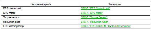
EPS Control Unit
• EPS control unit performs an arithmetical operation on data, such as steering wheel turning force (sensor signal) from the torque sensor, vehicle speed signal, etc. Then it generates an optimum assist torque signal to the EPS motor according to the driving condition.
• EPS control unit decreases the output signal to EPS motor while extremely using the power steering function (e.g., full steering) consecutively for protecting EPS motor and EPS control unit (Overload protection control).
• In SPORT mode, changes the steering assist characteristic to enhance a stable steering feel according to the mode signals from multi display unit via CAN communication. (Models with Nissan Dynamic Control System)
EPS Motor
EPS motor provides the assist torque by the control signal from EPS control u
Torque Sensor
Torque sensor detects the steering torque, and transmit the signal to EPS control unit.
Reduction Gear
Reduction gear increases the assist torque provided from EPS motor with worm gears, and outputs to the column shaft.

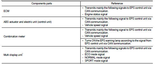
 System
EPS system : System Description
• EPS control unit performs an arithmetical operation on data, such
as steering wheel turning force (sensor signal) from the torque
sensor, vehicle speed signal, etc ...
Other materials:
Speed limiter main switch
Component Function Check
1.CHECK SPEED LIMITER MAIN SWITCH FUNCTION
With CONSULT-III
1. Turn ignition switch ON.
2. Select “ENGINE” using CONSULT-III.
3. Select “SL MAIN SW” in “DATA MONITOR” mode.
4. Check “SL MAIN SW” indication under the following condition.
Without CONSULT-III
1. Turn ...
B1150 curtain air bag module LH
DTC Logic
DTC DETECTION LOGIC
DTC CONFIRMATION PROCEDURE
1.CHECK SELF-DIAG RESULT
With CONSULT-III
1. Turn ignition switch ON.
2. Perform “Self Diagnostic Result” mode of “AIR BAG” using CONSULT-III.
Without CONSULT-III
1. Turn ignition switch ON.
2. Check the air bag warning lamp statu ...
Push-button ignition switch
Removal and Installation
REMOVAL
1. Remove the NATS antenna amp. Refer to SEC-167, "Removal and
Installation".
2. Remove the push-button ignition switch.
1. Disengage the push-button ignition switch fixing pawls
using minus driver etc.
2. Press the push-button ignition switch to ...
