Nissan Juke Service and Repair Manual : Combination switch
Exploded View
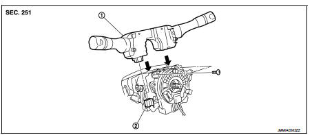
1. Combination switch 2. Combination switch connector
Removal and Installation
REMOVAL
1. Remove steering column cover. Refer to IP-13, "Removal and Installation".
2. Remove screws.
3. Disconnect the connector.
4. Pull up the combination switch to remove it.
INSTALLATION
Install in the reverse order of removal.
 BCM (body control module)
Removal and Installation
CAUTION:
Before replacing BCM, perform “READ CONFIGURATION” to save or print current
vehicle specification.
Refer to BCS-150, "Description".
REMOVAL (RHD MOD ...

Other materials:
Ecu diagnosis information
BCM
Reference Value
VALUES ON THE DIAGNOSIS TOOL
CONSULT-III MONITOR ITEM
TERMINAL LAYOUT
PHYSICAL VALUES
• *1: With manual A/C
• *2: RHD models
• *3: M/T models
• *4: LHD models
• *5: Except M/T models
Fail-safe
FAIL-SAFE CONTROL BY DTC
B ...
Front wiper auto stop signal circuit
Component Function Check
1.CHECK FRONT WIPER (AUTO STOP) SIGNAL
CONSULT-III DATA MONITOR
1. Select “WIP AUTO STOP” of IPDM E/R data monitor item.
2. Operate the front wiper.
3. With the front wiper operation, check the monitor status.
Is the status of item normal?
YES >> Auto stop sig ...
U1000 can comm circuit
Description
CAN (Controller Area Network) is a serial communication line for real time
application. It is an on-vehicle multiplex
communication line with high data communication speed and excellent error
detection ability. Many electronic
control units are equipped onto a vehicle, and each co ...
