Nissan Juke Service and Repair Manual : Coil spring
Exploded View
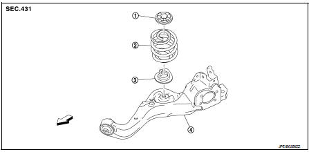
1. Upper rubber seat
2. Coil spring
3. Lower rubber seat
4. Suspension arm
 : Vehicle front
Removal and Installation
REMOVAL
1. Remove tires. Refer to WT-7, "Removal and Installation".
2. Remove wheel sensor and sensor harness. Refer to BRC-86, "REAR WHEEL SENSOR : Removal and Installation" (Without ESP), BRC-227, "REAR WHEEL SENSOR : Removal and Installation" (With ESP).
3. Set jack under suspension arm.
CAUTION:
• Never damage the suspension arm with a jack.
• Check the stable condition when using a jack.
4. Separate rear shock absorber lower side form suspension arm. Refer to RSU-8, "Removal and Installation".
5. Separate upper link from suspension arm.
6. Slowly lower jack, then remove upper rubber seat, coil spring and lower rubber seat from suspension arm.
CAUTION:
Operate while checking that jack supporting status is stable.
7. Perform inspection after removal. Refer to RSU-27, "Inspection" INSTALLATION
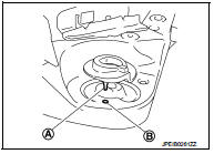
Note the following, and install in the reverse order of removal.
• Install the lower rubber seat a projection (A) is attached as suspension arm mounting hole (B).
• Match up lower rubber seat indentions and suspension arm grooves and attach.
• Perform inspection after installation. Refer to RSU-27, "Inspection".
Inspection
INSPECTION AFTER REMOVAL
Check lubber seat and coil spring for deformation, crack, and damage. Replace it if necessary.
INSPECTION AFTER INSTALLATION
1. Check wheel sensor harness for proper connection. Refer toBRC-85, "REAR WHEEL SENSOR : Exploded View" (Without ESP), BRC-225, "REAR WHEEL SENSOR : Exploded View" (With ESP).
2. Check wheel alignment. Refer to RSU-20, "Inspection".
 Rear shock absorber
Exploded View
1. Suspension arm
2. Shock absorber
3. Bound bumper
4. Bound bumper cover
5. Washer
6. Bushing
7. Distance tube
8. Piston rod lock nut
9. Cap
: Vehicle front
: Always r ...
 Suspension arm
Exploded View
1. Rear suspension member
2. Adjusting bolt
3. Upper link
4. Eccentric disk
5. Lower link
6. Suspension arm bracket
7. Suspension arm
: Vehicle front
: Always replace afte ...
Other materials:
Unlock sensor
Component Function Check
1.CHECK FUNCTION
1. Select “DOOR LOCK” of “BCM” using CONSULT-III.
2. Select “LOCK STATUS” in “DATA MONITOR” mode.
3. Check that the function operates normally according to the following
conditions.
Is the inspection result normal?
YES >> Unlock sensor is OK. ...
U1402 engine speed signal
DTC Logic
DTC DETECTION LOGIC
Diagnosis Procedure
1.PERFORM ECM SELF DIAGNOSIS
Using CONSULT-III, check the “self diagnosis result” of “ENGINE” and repair
or replace any malfunctioning
parts.
>> • Refer to EC-108, "DTC Index". (MR16DDT)
• Refer to EC-522, "DTC Index ...
P0100 MAF sensor
DTC Logic
DTC DETECTION LOGIC
Diagnosis Procedure
1.CHECK GROUND CONNECTIONS
1. Turn ignition switch OFF.
2. Check ground connection E38. Refer to Ground inspection in GI-44, "Circuit
Inspection".
Is the inspection result normal?
YES >> GO TO 2.
NO >> Repair or ...
