Nissan Juke Service and Repair Manual : Coil spring
Exploded View
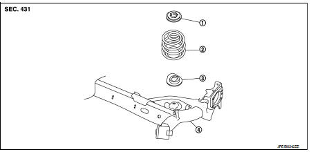
1. Upper rubber seat
2. Coil spring
3. Lower rubber seat
4. Rear suspension beam
Removal and Installation
REMOVAL
1. Remove tires. Refer to WT-7, "Removal and Installation".
2. Set jack under rear suspension beam.
CAUTION:
• Never damage the suspension beam with a jack.
• Check the stable condition when using a ja
ck.
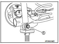
3. Remove rear shock absorber mounting bolts (lower side). Refer to RSU-8, "Exploded View".
4. Slowly lower jack, then remove upper rubber seat, coil spring and lower rubber seat from rear suspension beam.
CAUTION:
Operate while checking that jack supporting status is stable.
5. Perform inspection after removal. Refer to RSU-12, "Inspection".
INSTALLATION
Note the following, and install in the reverse order of removal.
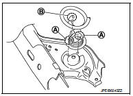
• Install lower rubber seat with its protrusion (A) on the lower area aligned with the hole of rear suspension beam.
• Securely install coil spring with the lower end (B) of the major diameter aligned with the steps of lower rubber seat.
• Perform inspection after installation. Refer to RSU-12, "Inspection".
Inspection
INSPECTION AFTER REMOVAL
Check lubber seat and coil spring for deformation, crack, and damage. Replace it if necessary.
INSPECTION AFTER INSTALLATION
Check wheel alignment. Refer to RSU-6, "Inspection".
 Rear shock absorber
Exploded View
1. Rear suspension beam
2. Shock absorber
3. Bound bumper
4. Bound bumper cover
5. Washer
6. Bushing
7. Distance tube
8. Piston rod lock nut
9. Cap
: Always replace aft ...
 Rear suspension beam
Exploded View
1. Rear suspension beam
2. Rear suspension arm bracket
: Always replace after every
disassembly.
: N·m (kg-m, ft-lb)
Removal and Installation
REMOVAL
1. Remove tires. Refer t ...
Other materials:
CVT position
Inspection and Adjustment
INSPECTION
1. Place selector lever in “P” position, and turn ignition switch ON (engine
stop).
2. Make sure that selector lever can be shifted to other than “P” position when
brake pedal is depressed. Also make sure that selector lever can be shifted from
“P” posit ...
Diagnosis system (BCM)
Common item
COMMON ITEM : CONSULT-III Function (BCM - COMMON ITEM)
APPLICATION ITEM
CONSULT-III performs the following functions via CAN communication with BCM.
SYSTEM APPLICATION
BCM can perform the following functions for each system.
NOTE:
It can perform the diagnosis modes except the ...
P0200 fuel injector
DTC Logic
DTC DETECTION LOGIC
Diagnosis Procedure
1.CHECK FUEL INJECTOR POWER SUPPLY CIRCUIT FOR OPEN AND SHORT
1. Turn ignition switch OFF.
2. Disconnect ECM harness connector.
3. Disconnect fuel injector harness connector.
4. Check the continuity between fuel injector harness connector an ...
