Nissan Juke Service and Repair Manual : Clutch pedal position switch
Component Function Check
1.CHECK FOR CLUTCH PEDAL POSITION SWITCH FUNCTION
1. Turn ignition switch ON.
2. Check the voltage between ECM harness connector and ground.
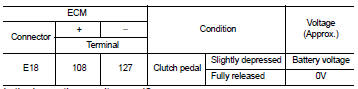
Is the inspection result normal? YES >> INSPECTION END.
NO >> Proceed to EC-427, "Diagnosis Procedure".
Diagnosis Procedure
1.CHECK CLUTCH PEDAL POSITION INPUT SIGNAL
1. Turn ignition switch OFF.
2. Disconnect clutch pedal position switch harness connector.
3. Turn ignition switch ON.
4. Check the voltage between clutch pedal position switch harness connector and ground.
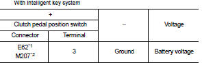
*1: LHD models
*2: RHD models
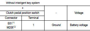
*1: LHD models
*2: RHD models
Is the inspection result normal? YES >> GO TO 3.
NO >> GO TO 2.
2.CHECK CLUTCH PEDAL POSITION SWITCH INPUT SIGNAL CIRCUIT
1. Turn ignition switch OFF.
2. Disconnect ECM harness connectors.
3. Check the continuity between clutch pedal position switch harness connector and ECM harness connector.
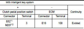
*1: LHD models
*2: RHD models
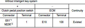
*1: LHD models
*2: RHD models
4. Also check harness for short to ground and to power.
Is the inspection result normal? YES >> Perform the trouble diagnosis for power supply circuit.
NO >> Repair or replace error-detected parts.
3.CHECK CLUTCH PEDAL POSITION SWITCH GROUND CIRCUIT
1. Turn ignition switch OFF.
2. Disconnect ECM harness connectors.
3. Check the continuity between clutch pedal position switch harness connector and ground
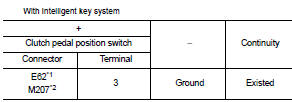
*1: LHD models
*2: RHD models
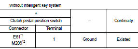
*1: LHD models
*2: RHD models
4. Also check harness for short to power.
Is the inspection result normal? YES >> GO TO 4.
NO >> Repair or replace error-detected parts.
4.CHECK CLUTCH PEDAL POSITION SWITCH
Check the clutch pedal position switch. Refer to EC-429, "Component Inspection".
Is the inspection result normal?
YES >> Check intermittent incident. Refer to GI-42, "Intermittent Incident".
NO >> Replace clutch pedal position switch. Refer to CL-16, "LHD : Exploded View" (LHD models) or CL- 18, "RHD : Exploded View" (RHD models).
Component Inspection
1.CHECK CLUTCH PEDAL POSITION SWITCH-I
1. Turn ignition switch OFF.
2. Disconnect clutch pedal position switch harness connector.
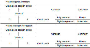
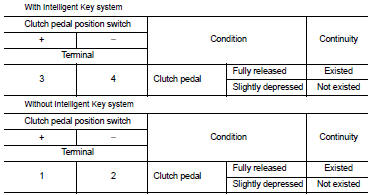
3. Check the continuity between clutch pedal position switch terminals as per the following conditions.
Is the inspection result normal? YES >> INSPECTION END
NO >> GO TO 2.
2.CHECK CLUTCH PEDAL POSITION SWITCH-II
1. Adjust clutch pedal position switch installation. Refer to CL-17, "LHD : Inspection and Adjustment" (LHD models) or CL-19, "RHD : Inspection and Adjustment" (RHD models).
2. Check the continuity between clutch pedal position switch terminals as per the following conditions.
Is the inspection result normal? YES >> INSPECTION END
NO >> Replace clutch pedal position switch. Refer to CL-16, "LHD : Exploded View" (LHD models) or CL- 18, "RHD : Exploded View" (RHD models).
 Brake pedal position switch
Component Function Check
1.CHECK BRAKE PEDAL POSITION SWITCH FUNCTION
With CONSULT-III
1. Turn ignition switch ON.
2. Select “BRAKE SW1” in “DATA MONITOR” mode of “ENGINE” using CONSULT-III.
3. C ...
 ASCD main switch
Component Function Check
1.CHECK ASCD MAIN SWITCH FUNCTION
With CONSULT-III
1. Turn ignition switch ON.
2. Select “MAIN SW” in “DATA MONITOR” mode of “ENGINE” using CONSULT-III.
3. Check “MAIN SW ...
Other materials:
System
Interior room lamp control system
INTERIOR ROOM LAMP CONTROL SYSTEM : System Diagram
INTERIOR ROOM LAMP CONTROL SYSTEM : System Description
OUTLINE
• Interior room lamps* are controlled by interior room lamp timer control
function of BCM.
*: Map lamp (when map lamp switch is in DOOR positio ...
Both side front fog lamps are not turned on
Description
The front fog lamps are not turned ON in any condition.
Diagnosis Procedure
1.CHECK FUSE
Check that the following fuse is fusing.
Is the inspection result normal?
YES >> GO TO 2.
NO >> Repair the applicable circuit. And then replace the fuse.
2.COMBINATION SWITC ...
P0014 EVT control
DTC Logic
DTC DETECTION LOGIC
NOTE:
If DTC P0014 is displayed with DTC P0078, first perform trouble diagnosis for
DTC P0078. Refer to EC-
585, "DTC Logic".
DTC CONFIRMATION PROCEDURE
1.PRECONDITIONING
If DTC Confirmation Procedure has been previously conducted, always perform
...
