Nissan Juke Service and Repair Manual : Center console assembly
Exploded View
CVT models
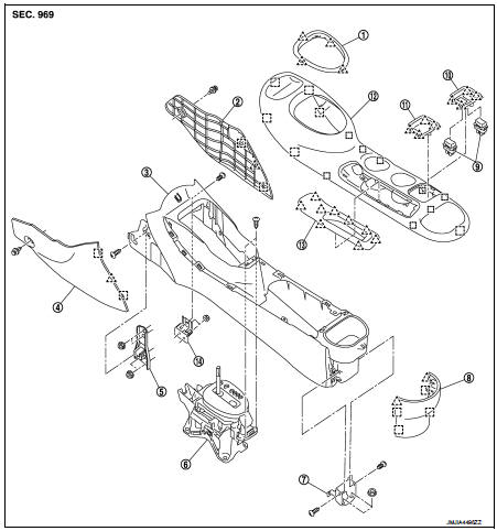
1. Console indicator finisher
2. Instrument lower cover RH
3. Center console assembly
4. Instrument lower cover LH
5. Instrument stay
6. CVT shift selector assembly
7. Console rear bracket
8. Console rear finisher
9. Seat heated switch
10. Console switch finisher
11. Console switch finisher
12. Console finisher assembly
13. Console mask
14. Console front bracket
 : Pawl
 : Metal clip
MT model
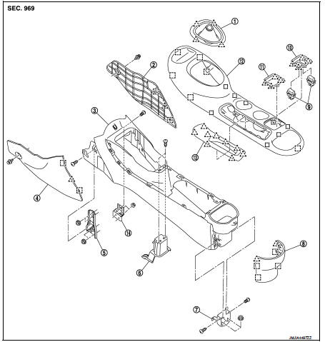
1. Console boot
2. Instrument lower cover RH
3. Center console assembly
4. Instrument lower cover LH
5. Instrument stay
6. Console center bracket
7. Console rear bracket
8. Console rear finisher
9. Seat heated switch
10. Console switch finisher
11. Console switch finisher
12. Console finisher assembly
13. Console mask
14. Console front bracket
 : Pawl
 : Metal clip
Removal and Installation
WARNING:
Before servicing, turn ignition switch OFF, disconnect battery negative terminal
and wait 3 minutes or
more.
REMOVAL
CAUTION:
When removing, always use a remover tool that is made of plastic.
1. Remove shift lever knob (MT models only).
• 5MT models: Refer to TM-25, "Removal and Installation".
• 6MT models: Refer to TM-78, "Removal and Installation".
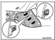
2. Remove console finisher assembly.
1. Put selector lever in “N” position.
2. Loosen the parking brake lever stroke by turning the adjusting nut with a socket wrench. Refer to PB- 2, "Inspection and Adjustment".
3. Lift up console finisher assembly in numerical order shown in the figure and disengage metal clips.
4. Remove console finisher assembly while pulling it towards vehicle rear.
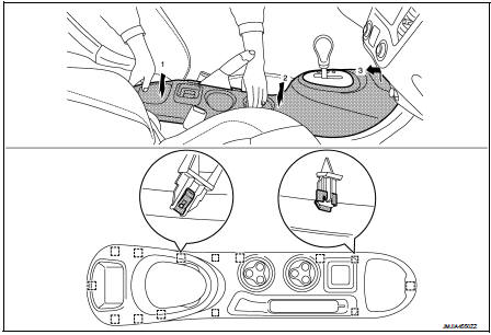
 : Metal clip
CAUTION:
• Be careful not for damaging parts in surrounding area.
• Remove metal clips slowly so that they are not damaged.
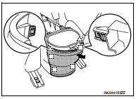
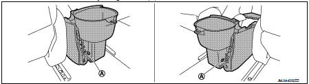
3. Remove console rear finisher.
1. Put front seat assembly (LH and RH) to frontmost position.
2. Pull back console rear finisher, and disengage the pawls and metal clips.
 : Pawl
 : Metal clip
4. Remove center console assembly fixing screws (A).
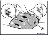
5. Remove instrument lower cover LH.
1. Put front seat assembly LH to rearmost position.
2. Remove fixing clip (A).
3. Pull the instrument lower cover LH crosswise, and disengage the pawl and metal clips.
CAUTION:
Remove pawl and metal clips slowly so that they are not
damaged.
 : Pawl
 : Metal clip
6. Remove instrument lower cover RH.
1. Put front seat assembly RH to rearmost position.
2. Remove fixing clip (A).
3. Pull the instrument lower cover RH crosswise, and disengage the pawl and metal clips.
CAUTION:
Remove pawl and metal clips slowly so that they are not
damaged.
 : Pawl
 : Metal clip
7. Remove center console assembly.
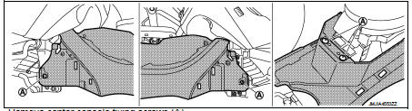
1. Remove center console fixing screws (A).
2. Lift up center console assembly back side.
CAUTION:
Be careful not for damaging parts in surrounding area.
INSTALLATION
Note the following item, and then install in the reverse order of removal.
CAUTION:
After installation, adjust the parking brake lever stroke. Refer to PB-2,
"Inspection and Adjustment".
Disassembly and Assembly
Disassembly and Assembly of Console Finisher Assembly
CAUTION
:
When disassembling, always use a remover tool that is made of plasti
c.
DISASSEMBLY
1. Remove console finisher assembly. Refer to IP-23, "Removal and Installation".
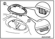
2. Remove console indicator finisher (CVT models)
Disengage connection of the console indicator finisher (2) fixing pawls from the inside of the console finisher assembly (1) toward the outside, and remove.
 : Pawl
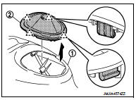
3. Remove console indicator finisher (MT models)
Disengage connection of the console boot (2) fixing pawls from the inside of the console finisher assembly (1) toward the outside, and remove.
 : Pawl
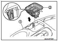
4. Remove console switch finisher.
Disengage connection of the console switch finisher (2) fixing pawls from the inside of the console finisher assembly (1) toward the outside, and remove.
NOTE
:
Remove seat heated switch. Refer to SE-51, "Removal and
Installation".
 : Pawl
ASSEMBLY
Assemble in the reverse order of disassembly.
 Instrument panel assembly
Exploded View
LHD models
1. Front passenger air bag module
2. Instrument panel assembly
3. Instrument side finisher LH
4. Combination meter
5. Cluster lid A
6. Push-button ignition switch ...
 Seat
Seat
...
Other materials:
P0488 EGR system
DTC Logic
DTC DETECTION LOGIC
Diagnosis Procedure
1.CHECK EGR VOLUME CONTROL VALVE CONTROL CIRCUIT
1. Turn ignition switch OFF.
2. Disconnect EGR volume control valve harness connector and ECM harness
connector.
3. Check the continuity between EGR volume control valve terminal harness
co ...
Wiring diagram
DOOR & LOCK SYSTEM
Wiring Diagram
For connector terminal arrangements, harness layouts, and alphabets in a
(option abbreviation; if not
described in wiring diagram), refer to GI-12, "Connector Information/Explanation
of Option Abbreviation".
...
B1087 seat belt Pre-tensioner LH
DTC Logic
DTC DETECTION LOGIC
DTC CONFIRMATION PROCEDURE
1.CHECK SELF-DIAG RESULT
With CONSULT-III
1. Turn ignition switch ON.
2. Perform “Self Diagnostic Result” mode of “AIR BAG” using CONSULT-III.
Without CONSULT-III
1. Turn ignition switch ON.
2. Check the air bag warning lamp statu ...
