Nissan Juke Service and Repair Manual : Camera image signal circuit
Description
• The NAVI control unit supplies power to the rear view camera when receiving a reverse signal.
• The rear view camera transmits camera images to the NAVI control unit when power is supplied from the NAVI control unit.
Diagnosis Procedure
1.CHECK CONTINUITY CAMERA POWER SUPPLY CIRCUIT
1. Turn ignition switch OFF.
2. Disconnect NAVI control unit connector and rear view camera connector.
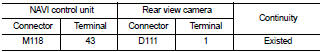
3. Check continuity between NAVI control unit harness connector and rear view camera harness connector.
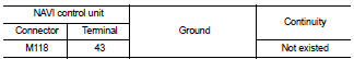
4. Check continuity between NAVI control unit harness connector and ground.
Is inspection result normal? YES >> GO TO 2.
NO >> Repair harness or connector.
2.CHECK VOLTAGE CAMERA POWER SUPPLY
1. Connect NAVI control unit connector and rear view camera connector.
2. Turn ignition switch ON.
3. Shift the selector lever to “R” position.
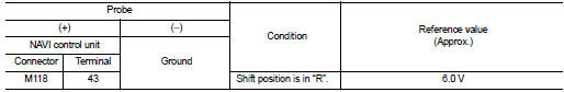
4. Check voltage between NAVI control unit harness connector and ground.
Is inspection result normal? YES >> GO TO 3.
NO >> Replace NAVI control unit. Refer to AV-84, "Removal and Installation".
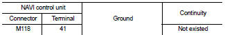
3.CHECK CONTINUITY CAMERA IMAGE SIGNAL CIRCUIT
1. Turn ignition switch OFF.
2. Disconnect NAVI control unit connector and rear view camera connector.
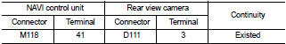
3. Check continuity between NAVI control unit harness connector and rear view camera harness connector.
4. Check continuity between NAVI control unit harness connector and ground.
Is inspection result normal? YES >> GO TO 4.
NO >> Repair harness or connector.
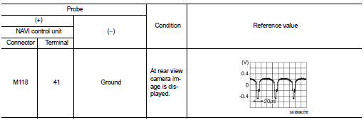
4.CHECK CAMERA IMAGE SIGNAL
1. Connect NAVI control unit connector and rear view camera connector.
2. Turn ignition switch ON.
3. Shift the selector lever to “R” position.
4. Check signal between NAVI control unit harness connector and ground.
Is inspection result normal? YES >> Replace NAVI control unit. Refer to AV-84, "Removal and Installation".
NO >> Replace rear view camera. Refer to AV-92, "Removal and Installation".
 Microphone signal circuit
Description
Power is supplied from NAVI control unit to microphone. The microphone
transmits the sound voice to the
NAVI control unit.
Diagnosis Procedure
1.CHECK CONTINUITY BETWEEN NAVI CONTROL ...
 Steering switch signal A circuit
Description
Transmits the steering switch signal to NAVI control unit.
Diagnosis Procedure
1.CHECK STEERING SWITCH SIGNAL A CIRCUIT
1. Disconnect NAVI control unit connector and spiral cable conne ...
Other materials:
B2098 ignition relay on stuck
Description
• IPDM E/R operates the ignition relay when it receives an ignition switch ON
signal from BCM via CAN communication.
• Turn the ignition relay OFF by pressing the push-button ignition switch once
when the vehicle speed is 4 km/
h (2.5 MPH) or less.
• Turn the ignition relay OFF w ...
Wheelarch Height
2WD
Measure value under unladen* conditions.
*: Fuel, engine coolant and lubricant are full. Spare tire, jack, hand tools and
mats are in designated positions.
4WD
Measure value under unladen* conditions.
*: Fuel, engine coolant and lubricant are full. Spare tire, jack, hand t ...
B1058, B1059, B1060, B1061, B1062, B1063 diagnosis sensor unit
DTC Logic
DTC DETECTION LOGIC
DTC CONFIRMATION PROCEDURE
1.CHECK SELF-DIAG RESULT
With CONSULT-III
1. Turn ignition switch ON.
2. Perform “Self Diagnostic Result” mode of “AIR BAG” using CONSULT-III.
Without CONSULT-III
1. Turn ignition switch ON.
2. Check the air bag warning lamp statu ...
