Nissan Juke Service and Repair Manual : C1601 battery power supply
DTC Logic
DTC DETECTION LOGIC
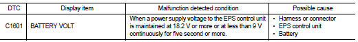
DTC CONFIRMATION PROCEDURE
1.PRECONDITIONING
If “DTC CONFIRMATION PROCEDURE” has been previously conducted, always turn ignition switch OFF and wait at least 10 seconds before conducting the next test.
>> GO TO 2.
2.DTC REPRODUCTION PROCEDURE
 With CONSULT-III
1. Turn the ignition switch OFF to ON.
2. Perform “EPS” self-diagnosis.
Is DTC “C1601” detected? YES >> Proceed to diagnosis procedure. Refer to STC-19, "Diagnosis Procedure".
NO >> INSPECTION EN
Diagnosis Procedure
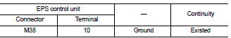
1.CHECK EPS CONTROL UNIT GROUND CIRCUIT
1. Turn ignition switch OFF.
2. Disconnect EPS control unit harness connector.
3. Check continuity between EPS control unit harness connector terminal and ground.
4. Connect EPS control unit harness connector.
Is the inspection result normal? YES >> GO TO 2.
NO >> Repair open circuit or short to ground or short to power in harness or connectors.
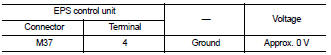
2.CHECK EPS CONTROL UNIT POWER SUPPLY CIRCUIT (1)
1. Check voltage between EPS control unit harness connector terminals and ground.
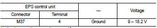
2. Turn ignition switch ON.
CAUTION:
Never start the engine
.
3. Check voltage between EPS control unit harness connector and ground.
Is the inspection result normal? YES >> GO TO 4.
NO >> GO TO 3.
3.CHECK EPS CONTROL UNIT POWER SUPPLY CIRCUIT (2)
1. Turn ignition switch OFF.
2. Check the 10A fuse (#3).
3. Check the harness for open or short between EPS control unit harness connector No.4 terminal and the 10A fuse (#3).
Is the inspection result normal? YES >> Perform the trouble diagnosis for ignition power supply circuit. Refer to PG-15, "Wiring Diagram - IGNITION POWER SUPPLY -".
NO >> Repair or replace error-detected parts.
4.CHECK EPS CONTROL UNIT POWER SUPPLY CIRCUIT (3)
1. Turn ignition switch OFF.
2. Check voltage between EPS control unit harness connector terminals and ground.
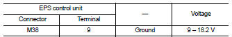
3. Turn ignition switch ON.
CAUTION:
Never start the engine.
4. Check voltage between EPS control unit harness connector and ground.
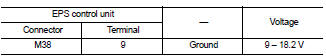
Is the inspection result normal? YES >> GO TO 6.
NO >> GO TO 5.
5.CHECK EPS CONTROL UNIT POWER SUPPLY CIRCUIT (4)
1. Turn ignition switch OFF.
2. Check the 60A fusible link (M).
3. Check the harness for open or short between EPS control unit harness connector No.9 terminal and the 60A fusible link (M).
Is the inspection result normal? YES >> Perform the trouble diagnosis for power supply circuit. Refer to PG-10, "Wiring Diagram - BATTERY POWER SUPPLY -".
NO >> Repair or replace error-detected parts.
6.CHECK TERMINALS AND HARNESS CONECTORS
Check the EPS control unit pin terminals for damage or loose connection with harness connector.
Is the inspection result normal? YES >> EPS control unit is malfunctioning. Replace steering column assembly. Refer to ST-10, "Removal and Installation".
NO >> Repair or replace error-detected parts.

 C1604 torque sensor
DTC Logic
DTC DETECTION LOGI
DTC CONFIRMATION PROCEDURE
1.PRECONDITIONING
If “DTC CONFIRMATION PROCEDURE” has been previously conducted, always turn
ignition switch OFF and
wait at least 10 s ...
Other materials:
P1217 engine over temperature
DTC Logic
DTC DETECTION LOGIC
NOTE:
• If DTC P1217 is displayed with DTC UXXXX, first perform the trouble diagnosis
for DTC UXXXX.
• If DTC P1217 is displayed with DTC P0607, first perform the trouble diagnosis
for DTC P0607. Refer
to EC-304, "DTC Logic".
If the cooling fan or ...
Back door does not opened
Diagnosis Procedure
1.CHECK BACK DOOR OPENER SWITCH
Check back door opener switch.
Refer to DLK-244, "Component Function Check".
Is the inspection result normal?
YES >> GO TO 2.
NO >> Repair or replace the malfunctioning parts.
2.CHECK BACK DOOR OPENER ACTUATOR
...
Clutch piping
Exploded View
RS5F92R
1. CSC (Concentric Slave Cylinder)
2. Clutch tube
3. Clutch damper
4. Bracket
5. Master cylinder
RS6F94R
1. CSC (Concentric Slave Cylinder)
2. Clutch tube
3. Clutch damper
4. Bracket
5. Master cylinder
Hydraulic Layout
1. Clutch tube
2. Lock pin
3. ...
