Nissan Juke Service and Repair Manual : C1121, C1123, C1125, C1127 ABS out valve system
DTC Logic
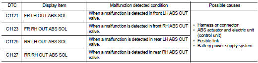
DTC DETECTION LOGIC
DTC CONFIRMATION PROCEDURE
1.PRECONDITIONING
If “DTC CONFIRMATION PROCEDURE” has been previously conducted, always turn ignition switch OFF and wait at least 10 seconds before conducting the next test.
>> GO TO 2.
2.CHECK DTC DETECTION
 With CONSULT-III
1. Turn the ignition switch OFF to ON.
2. Perform self-diagnosis for “ABS”.
Is DTC “C1121”, “C1123”, “C1125” or “C1127” detected? YES >> Proceed to BRC-58, "Diagnosis Procedure".
NO >> INSPECTION END
Diagnosis Procedure
1.CHECK CONNECTOR
1. Turn the ignition switch OFF.
2. Check ABS actuator and electric unit (control unit) harness connector for disconnection or looseness.
Is the inspection result normal? YES >> GO TO 3.
NO >> Repair or replace error-detected parts, securely lock the connector, and GO TO 2.
2.PERFORM SELF-DIAGNOSIS
Perform self-diagnosis for “ABS” again.
Is DTC “C1121”, “C1123”, “C1125” or “C1127” detected? YES >> GO TO 3.
NO >> INSPECTION END
3.CHECK ABS OUT VALVE POWER SUPPLY
1. Turn the ignition switch OFF.
2. Disconnect ABS actuator and electric unit (control unit) harness connector.
3. Check voltage between ABS actuator and electric unit (control unit) harness connector and ground.
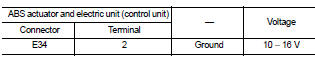
4. Turn the ignition switch ON.
CAUTION:
Never start engine.
5. Check voltage between ABS actuator and electric unit (control unit) harness connector and ground.
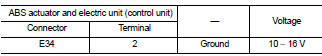
Is the inspection result normal? YES >> GO TO 5.
NO >> GO TO 4.
4.CHECK ABS OUT VALVE POWER SUPPLY CIRCUIT
1. Turn the ignition switch OFF.
2. Check 40 A fusible link (F).
3. Check continuity and short circuit between ABS actuator and electric unit (control unit) harness connector terminal (2) and 40 A fusible link (F).
Is the inspection result normal? YES >> Perform trouble diagnosis for battery power supply. Refer to PG-10, "Wiring Diagram - BATTERY POWER SUPPLY -".
NO >> Repair or replace error-detected parts.
5.CHECK ABS OUT VALVE GROUND CIRCUIT
1. Turn the ignition switch OFF.
2. Check continuity between ABS actuator and electric unit (control unit) harness connector and the ground.
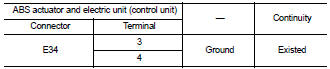
Is the inspection result normal? YES >> GO TO 6.
NO >> Repair or replace error-detected parts.
6.CHECK TERMINAL
Check ABS actuator and electric unit (control unit) pin terminals for damage or loose connection with harness connector.
Is the inspection result normal? YES >> Replace ABS actuator and electric unit (control unit). Refer to BRC-90, "Removal and Installation".
NO >> Repair or replace error-detected parts.
 C1120, C1122, C1124, C1126 ABS in valve system
DTC Logic
DTC DETECTION LOGIC
DTC CONFIRMATION PROCEDURE
1.PRECONDITIONING
If “DTC CONFIRMATION PROCEDURE” has been previously conducted, always turn
ignition switch OFF and
wait at least 10 ...
 C1140 actuator relay system
DTC Logic
DTC DETECTION LOGIC
DTC CONFIRMATION PROCEDURE
1.PRECONDITIONING
If “DTC CONFIRMATION PROCEDURE” has been previously conducted, always turn
ignition switch OFF and
wait at least 10 ...
Other materials:
Throttle valve closed position
learning
Description
Throttle Valve Closed Position Learning is a function of ECM to learn the
fully closed position of the throttle
valve by monitoring the throttle position sensor output signal. It must be
performed each time the harness connector
of the electric throttle control actuator or ECM is ...
Power door lock system
System Diagram
System Description
DOOR LOCK FUNCTION
• The door lock and unlock switch (driver side) is build into power window
main switch.
• Interlocked with the locking operation of door lock and unlock switch, door
lock actuators of all doors are
locked.
• Interlocked with the unlock ...
Unbalance steering wheel turning force and return between
right and left
Description
Unbalance steering wheel turning force and return between right and left.
Diagnosis Procedure
1.CHECK THE ILLUMINATION OF THE EPS WARNING LAMP
Check the EPS warning lamp while engine is running.
Does the EPS warning lamp turn OFF?
YES >> GO TO 2.
NO >> Refer to STC ...
