Nissan Juke Service and Repair Manual : C1116 stop lamp switch
DTC Logic
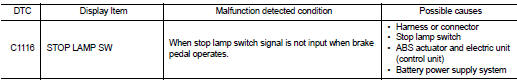
DTC DETECTION LOGIC
DTC CONFIRMATION PROCEDURE
1.PRECONDITIONING
If “DTC CONFIRMATION PROCEDURE” has been previously conducted, always turn ignition switch OFF and wait at least 10 seconds before conducting the next test.
>> GO TO 2.
2.CHECK DTC DETECTION
 With CONSULT-III.
1. Turn the ignition switch OFF to ON.
2. Perform self-diagnosis for “ABS”.
Is DTC “C1116” detected? YES >> Proceed to BRC-174, "Diagnosis Procedure".
NO >> INSPECTION END
Diagnosis Procedure
NOTE
:
DTC “C1116” may be detected when the brake pedal and the accelerator pedal are
simultaneously depressed
for 1 minute or more while driving the vehicle. This is not a malfunction.
1.INTERVIEW FROM THE CUSTOMER
Check if the brake pedal and the accelerator pedal are simultaneously depressed for 1 minute or more while driving the vehicle.
Is there such a history? YES >> GO TO 2.
NO >> GO TO 3.
2.PERFORM SELF-DIAGNOSIS
With CONSULT-III.
1. Erase Self-diagnosis result for “ABS”.
2. Turn the ignition switch OFF, and wait 10 seconds or more.
3. Start the engine.
CAUTION:
Never start the vehicle.
4. Depress the brake pedal several times.
5. Perform self-diagnosis for “ABS”.
Is DTC “C1116” detected? YES >> GO TO 3.
NO >> INSPECTION END
3.STOP LAMP FOR ILLUMINATION
Depress brake pedal and check that stop lamp turns ON.
Does stop lamp turn ON?
YES >> GO TO 5.
NO >> Check stop lamp system. Refer to EXL-39, "Wiring Diagram". GO TO 4.
4.CHECK DATA MONITOR (1)
With CONSULT-III.
1. Erase Self-diagnosis result for “ABS”.
2. Turn the ignition switch OFF, and wait 10 seconds or more.
3. Start the engine.
CAUTION:
Never start the vehicle.
4. Select “ABS”, “DATA MONITOR” and “STOP LAMP SW” according to this order. Check that data monitor displays “On” or “Off” when brake pedal is depress or release. Refer to BRC-136, "Reference Value".
Is the inspection result normal? YES >> INSPECTION END
NO >> GO TO 5.
5.CHECK STOP LAMP SWITCH CLEARANCE
1. Turn the ignition switch OFF.
2. Check stop lamp switch clearance.
- LHD: Refer to BR-9, "Inspection and Adjustment".
- RHD: Refer to BR-77, "Inspection and Adjustment".
Is the inspection result normal? YES >> GO TO 7.
NO >> Adjust stop lamp switch clearance. GO TO 6.
• LHD: Refer to BR-77, "Inspection and Adjustment".
• RHD: Refer to BR-77, "Inspection and Adjustment".
6.CHECK DATA MONITOR (2)
With CONSULT-III.
1. Erase Self-diagnosis result for “ABS”.
2. Turn the ignition switch OFF, and wait 10 seconds or more.
3. Start the engine.
CAUTION:
Never start the vehicle.
4. Select “ABS”, “DATA MONITOR” and “STOP LAMP SW” according to this order. Check that data monitor displays “On” or “Off” when brake pedal is depress or release. Refer to BRC-136, "Reference Value".
Is the inspection result normal? YES >> INSPECTION END
NO >> GO TO 7.
7.CHECK STOP LAMP SWITCH
Check stop lamp switch. Refer to BRC-177, "Component Inspection".
Is the inspection result normal? YES >> GO TO 9.
NO >> Replace stop lamp switch. GO TO 8.
• LHD: Refer to BR-21, "Removal and Installation".
• RHD: Refer to BR-89, "Removal and Installation".
8.CHECK DATA MONITOR (3)
With CONSULT-III.
1. Erase Self-diagnosis result for “ABS”.
2. Turn the ignition switch OFF, and wait 10 seconds or more.
3. Start the engine.
CAUTION:
Never start the vehicle.
4. Select “ABS”, “DATA MONITOR” and “STOP LAMP SW” according to this order. Check that data monitor displays “On” or “Off” when brake pedal is depress or release. Refer to BRC-136, "Reference Value".
Is the inspection result normal?
YES >> INSPECTION END
NO >> GO TO 9.
9.CHECK CONNECTOR AND TERMINAL
1. Turn the ignition switch OFF.
2. Disconnect ABS actuator and electric unit (control unit) harness connector.
3. Check ABS actuator and electric unit (control unit) harness connector for disconnection or looseness.
4. Check ABS actuator and electric unit (control unit) pin terminals for damage or loose connection with harness connector.
5. Disconnect stop lamp switch harness connector.
6. Check stop lamp switch harness connector for disconnection or looseness.
7. Check stop lamp switch pin terminals for damage or loose connection with harness connector.
Is the inspection result normal? YES >> GO TO 11.
NO >> Repair or replace error-detected parts. GO TO 10.
10.CHECK DATA MONITOR (4)
 With CONSULT-III.
1. Connect ABS actuator and electric unit (control unit) harness connector.
2. Connect stop lamp switch harness connector.
3. Erase Self-diagnosis result for “ABS”.
4. Turn the ignition switch OFF, and wait 10 seconds or more.
5. Start the engine.
CAUTION:
Never start the vehicle.
6. Select “ABS”, “DATA MONITOR” and “STOP LAMP SW” according to this order. Check that data monitor displays “On” or “Off” when brake pedal is depress or release. Refer to BRC-136, "Reference Value".
Is the inspection result normal? YES >> INSPECTION END
NO >> GO TO 11.
11.CHECK STOP LAMP SWITCH CIRCUIT (1)
1. Turn the ignition switch OFF.
2. Disconnect ABS actuator and electric unit (control unit) harness connector.
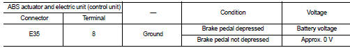
3. Check voltage between ABS actuator and electric unit (control unit) harness connector and ground.
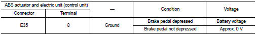
4. Turn the ignition switch ON.
5. Check voltage between ABS actuator and electric unit (control unit) harness connector and ground.
Is the inspection result normal? YES >> Replace ABS actuator and electric unit (control unit). Refer to BRC-233, "Removal and Installation".
NO >> Repair or replace error-detected parts. GO TO 12.
12.CHECK STOP LAMP SWITCH CIRCUIT (2)
1. Turn the ignition switch OFF.
2. Disconnect stop lamp switch harness connector.
3. Check continuity between ABS actuator and electric unit (control unit) harness connector and stop lamp switch harness connector.
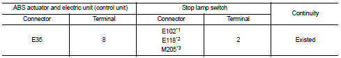
*1: Models with CVT
*2: LHD models with M/T
*3: RHD models with M/T
4. Check continuity between ABS actuator and electric unit (control unit) harness connector and the ground.
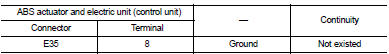
Is the inspection result normal? YES >> Replace ABS actuator and electric unit (control unit). Refer to BRC-233, "Removal and Installation".
NO >> Repair or replace error-detected parts. GO TO 13.
13.CHECK DATA MONITOR (5)
 With CONSULT-III.
1. Connect ABS actuator and electric unit (control unit) harness connector.
2. Connect stop lamp switch harness connector.
3. Erase Self-diagnosis result for “ABS”.
4. Turn the ignition switch OFF, and wait 10 seconds or more.
5. Start the engine.
CAUTION:
Never start the vehicle.
6. Select “ABS”, “DATA MONITOR” and “STOP LAMP SW” according to this order. Check that data monitor displays “On” or “Off” when brake pedal is depress or release. Refer to BRC-136, "Reference Value".
Is the inspection result normal? YES >> INSPECTION END
NO >> Replace ABS actuator and electric unit (control unit). Refer to BRC-233, "Removal and Installation".
Component Inspection
1.CHECK STOP LAMP SWITCH
1. Turn the ignition switch OFF.
2. Disconnect stop lamp switch harness connector.
3. Check continuity when stop lamp switch is operated.
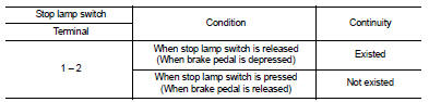
Is the inspection result normal? YES >> INSPECTION END
NO >> Replace stop lamp switch.
• LHD: Refer to BR-21, "Removal and Installation".
• RHD: Refer to BR-89, "Removal and Installation".
 C1115 wheel sensor
DTC Logic
DTC CONFIRMATION PROCEDURE
1.PRECONDITIONING
If “DTC CONFIRMATION PROCEDURE” has been previously conducted, always turn
ignition switch OFF and
wait at least 10 seconds before conduc ...
 C1120, C1122, C1124, C1126 ABS in valve system
DTC Logic
DTC DETECTION LOGIC
DTC CONFIRMATION PROCEDURE
1.PRECONDITIONING
If “DTC CONFIRMATION PROCEDURE” has been previously conducted, always turn
ignition switch OFF and
wait at least 10 ...
Other materials:
Steering wheel turning force is heavy or light
Description
Steering wheel turning force is heavy or light.
Diagnosis Procedure
1.CHECK THE ILLUMINATION OF THE EPS WARNING LAMP
Check that the EPS warning lamp turns ON when ignition switch turns ON. Then,
EPS warning lamp turns
OFF after the engine is started.
Is the inspection result no ...
Coil spring
Exploded View
1. Upper rubber seat
2. Coil spring
3. Lower rubber seat
4. Suspension arm
: Vehicle front
Removal and Installation
REMOVAL
1. Remove tires. Refer to WT-7, "Removal and Installation".
2. Remove wheel sensor and sensor harness. Refer to BRC-86, "REAR WHEEL SE ...
P0172 fuel injection system function
DTC Logic
DTC DETECTION LOGIC
With the Air/Fuel Mixture Ratio Self-Learning Control, the actual mixture
ratio can be brought closely to the
theoretical mixture ratio based on the mixture ratio feedback signal from the
A/F sensors 1. The ECM calculates
the necessary compensation to correct th ...
