Nissan Juke Service and Repair Manual : C1105, C1106, C1107, C1108 wheel sensor
DTC Logic
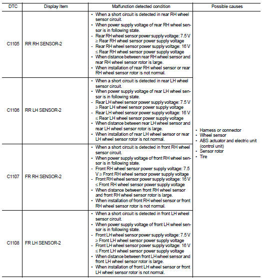
DTC DETECTION LOGIC
DTC CONFIRMATION PROCEDURE
1.PRECONDITIONING
If “DTC CONFIRMATION PROCEDURE” has been previously conducted, always turn ignition switch OFF and wait at least 10 seconds before conducting the next test.
>> GO TO 2.
2.CHECK DTC DETECTION
 With CONSULT-III.
1. Stat the engine.
2. Drive the vehicle at approx. 30 km/h (19 MPH) or more for approx. 1 minute.
3. Stop the vehicle.
4. Perform self-diagnosis for “ABS”.
Is DTC “C1105”, “C1106”, “C1107” or “C1108” detected? YES >> Proceed to BRC-155, "Diagnosis Procedure".
NO >> INSPECTION END
Diagnosis Procedure
CAUTION:
Never check between wheel sensor harness connector terminals.
1.CHECK ABS ACTUATOR AND ELECTRIC UNIT (CONTROL UNIT) POWER SUPPLY SYSTEM
Check ABS actuator and electric unit (control unit) power supply system. Refer to BRC-205, "Diagnosis Procedure".
Is the inspection result normal? YES >> GO TO 2.
NO >> Repair or replace error-detected parts.
2.CHECK TIRE
1. Turn the ignition switch OFF.
2. Check tire air pressure, wear and size. Refer to WT-9, "Tire Air Pressure".
Is the inspection result normal? YES >> GO TO 5.
NO >> Adjust air pressure or replace tire and GO TO 3.
3.CHECK DATA MONITOR (1)
 With CONSULT-III.
1. Erase Self-diagnosis result for “ABS”.
2. Turn the ignition switch OFF, and wait 10 seconds or more.
3. Stat the engine.
4. Select “ABS” and “DATA MONITOR”, check “FR LH SENSOR”, “FR RH SENSOR”, “RR LH SENSOR” and “RR RH SENSOR”.
NOTE
:
Set the “DATA MONITOR” recording speed to “10 msec”.
5. Read a value (wheel speed) of both normal wheel sensors and error-detecting wheel sensor.
Regarding the deference at 30 km/h (19 MPH) between the wheel speed detected by the error detecting wheel sensor and the maximum/minimum wheel speed detected by the normal wheel sensors, is the difference within 5%, respectively? YES >> GO TO 4.
NO >> GO TO 5.
4.PERFORM SELF-DIAGNOSIS (1)
 With CONSULT-III.
1. Drive the vehicle at approx. 30 km/h (19 MPH) or more for approx. 1 minute.
2. Stop the vehicle.
3. Perform self-diagnosis for “ABS”.
Is DTC “C1105”, “C1106”, “C1107” or “C1108” detected? YES >> GO TO 5.
NO >> INSPECTION END
5.CHECK WHEEL SENSOR
1. Turn the ignition switch OFF.
2. Check wheel sensor for damage.
3. Remove dust and foreign matter adhered to the sensor rotor with a vacuum dust collector through the wheel sensor mounting hole.
CAUTION:
Install wheel sensor with no backlash and float, and tighten the mounting bolt
to the specified
torque.
• Front: Refer to BRC-224, "FRONT WHEEL SENSOR : Exploded View".
• Rear: Refer to BRC-225, "REAR WHEEL SENSOR : Exploded View".
Is the inspection result normal? YES >> GO TO 8.
NO >> GO TO 6.
6.REPLACE WHEEL SENSOR (1)
With CONSULT-III.
1. Replace wheel sensor.
- Front: Refer to BRC-224, "FRONT WHEEL SENSOR : Removal and Installation".
- Rear: Refer to BRC-227, "REAR WHEEL SENSOR : Removal and Installation".
2. Erase Self-diagnosis result for “ABS”.
3. Turn the ignition switch OFF, and wait 10 seconds or more.
4. Stat the engine.
5. Select “ABS” and “DATA MONITOR”, check “FR LH SENSOR”, “FR RH SENSOR”, “RR LH SENSOR” and “RR RH SENSOR”.
NOTE
:
Set the “DATA MONITOR” recording speed to “10 msec”.
6. Read a value (wheel speed) of both normal wheel sensors and error-detecting wheel sensor.
Regarding the deference at 30 km/h (19 MPH) between the wheel speed detected by the error detecting wheel sensor and the maximum/minimum wheel speed detected by the normal wheel sensors, is the difference within 5%, respectively? YES >> GO TO 7.
NO >> GO TO 19.
7.PERFORM SELF-DIAGNOSIS (2)
With CONSULT-III.
1. Drive the vehicle at approx. 30 km/h (19 MPH) or more for approx. 1 minute.
2. Stop the vehicle.
3. Perform self-diagnosis for “ABS”.
Is DTC “C1105”, “C1106”, “C1107” or “C1108” detected? YES >> GO TO 19.
NO >> INSPECTION END
8.CHECK CONNECTOR
1. Turn the ignition switch OFF.
2. Check ABS actuator and electric unit (control unit) harness connector for disconnection or looseness.
3. Check wheel sensor harness connector for disconnection or looseness.
Is the inspection result normal? YES >> GO TO 11.
NO >> Repair or replace error-detected parts, securely lock the connector, and GO TO 9.
9.CHECK DATA MONITOR (2)
With CONSULT-III.
1. Erase Self-diagnosis result for “ABS”.
2. Turn the ignition switch OFF, and wait 10 seconds or more.
3. Stat the engine.
4. Select “ABS” and “DATA MONITOR”, check “FR LH SENSOR”, “FR RH SENSOR”, “RR LH SENSOR” and “RR RH SENSOR”.
NOTE
:
Set the “DATA MONITOR” recording speed to “10 msec”.
5. Read a value (wheel speed) of both normal wheel sensors and error-detecting wheel sensor.
Regarding the deference at 30 km/h (19 MPH) between the wheel speed detected by the error detecting wheel sensor and the maximum/minimum wheel speed detected by the normal wheel sensors, is the difference within 5%, respectively? YES >> GO TO 10.
NO >> GO TO 11.
10.PERFORM SELF-DIAGNOSIS (3)
With CONSULT-III.
1. Drive the vehicle at approx. 30 km/h (19 MPH) or more for approx. 1 minute.
2. Stop the vehicle.
3. Perform self-diagnosis for “ABS”.
Is DTC “C1105”, “C1106”, “C1107” or “C1108” detected? YES >> GO TO 11.
NO >> INSPECTION END
11.CHECK TERMINAL
1. Turn the ignition switch OFF.
2. Disconnect ABS actuator and electric unit (control unit) harness connector and then check ABS actuator and electric unit (control unit) pin terminals for damage or loose connection with harness connector.
3. Disconnect wheel sensor harness connector and check each wheel sensor pin terminals for damage or loose connection with harness connector.
Is the inspection result normal? YES >> GO TO 14.
NO >> Repair or replace error-detected parts and GO TO 12.
12.CHECK DATA MONITOR (3)
With CONSULT-III.
1. Connect ABS actuator and electric unit (control unit) harness connector.
2. Connect wheel sensor harness connector.
3. Erase Self-diagnosis result for “ABS”.
4. Turn the ignition switch OFF, and wait 10 seconds or more.
5. Stat the engine.
6. Select “ABS” and “DATA MONITOR”, check “FR LH SENSOR”, “FR RH SENSOR”, “RR LH SENSOR” and “RR RH SENSOR”.
NOTE
:
Set the “DATA MONITOR” recording speed to “10 msec”.
7. Read a value (wheel speed) of both normal wheel sensors and error-detecting wheel sensor.
Regarding the deference at 30 km/h (19 MPH) between the wheel speed detected by the error detecting wheel sensor and the maximum/minimum wheel speed detected by the normal wheel sensors, is the difference within 5%, respectively? YES >> GO TO 13.
NO >> GO TO 14.
13.PERFORM SELF-DIAGNOSIS (4)
With CONSULT-III.
1. Drive the vehicle at approx. 30 km/h (19 MPH) or more for approx. 1 minute.
2. Stop the vehicle.
3. Perform self-diagnosis for “ABS”.
Is DTC “C1105”, “C1106”, “C1107” or “C1108” detected? YES >> GO TO 14.
NO >> INSPECTION END
14.CHECK WHEEL SENSOR HARNESS
1. Turn the ignition switch OFF.
2. Disconnect ABS actuator and electric unit (control unit) harness connector.
3. Disconnect wheel sensor harness connector.
4. Check continuity between ABS actuator and electric unit (control unit) harness connector and the ground.
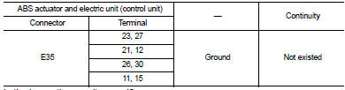
Is the inspection result normal? YES >> GO TO 15.
NO >> Repair or replace error-detected parts and GO TO 15.
15.CHECK DATA MONITOR (4)
With CONSULT-III.
1. Connect ABS actuator and electric unit (control unit) harness connector.
2. Connect wheel sensor harness connector.
3. Erase Self-diagnosis result for “ABS”.
4. Turn the ignition switch OFF, and wait 10 seconds or more.
5. Stat the engine.
6. Select “ABS” and “DATA MONITOR”, check “FR LH SENSOR”, “FR RH SENSOR”, “RR LH SENSOR” and “RR RH SENSOR”.
NOTE
:
Set the “DATA MONITOR” recording speed to “10 msec”.
7. Read a value (wheel speed) of both normal wheel sensors and error-detecting wheel sensor.
Regarding the deference at 30 km/h (19 MPH) between the wheel speed detected by the error detecting wheel sensor and the maximum/minimum wheel speed detected by the normal wheel sensors, is the difference within 5%, respectively? YES >> GO TO 16.
NO >> GO TO 17.
16.PERFORM SELF-DIAGNOSIS (5)
With CONSULT-III.
1. Drive the vehicle at approx. 30 km/h (19 MPH) or more for approx. 1 minute.
2. Stop the vehicle.
3. Perform self-diagnosis for “ABS”.
Is DTC “C1105”, “C1106”, “C1107” or “C1108” detected? YES >> GO TO 17.
NO >> INSPECTION END
17.REPLACE WHEEL SENSOR
With CONSULT-III.
1. Replace wheel sensor.
- Front: Refer to BRC-224, "FRONT WHEEL SENSOR : Removal and Installation".
- Rear: Refer to BRC-227, "REAR WHEEL SENSOR : Removal and Installation".
2. Erase Self-diagnosis result for “ABS”.
3. Turn the ignition switch OFF, and wait 10 seconds or more.
4. Stat the engine.
5. Select “ABS” and “DATA MONITOR”, check “FR LH SENSOR”, “FR RH SENSOR”, “RR LH SENSOR” and “RR RH SENSOR”.
NOTE
:
Set the “DATA MONITOR” recording speed to “10 msec”.
6. Read a value (wheel speed) of both normal wheel sensors and error-detecting wheel sensor.
Regarding the deference at 30 km/h (19 MPH) between the wheel speed detected by the error detecting wheel sensor and the maximum/minimum wheel speed detected by the normal wheel sensors, is the difference within 5%, respectively? YES >> GO TO 18.
NO >> GO TO 19.
18.PERFORM SELF-DIAGNOSIS (6)
With CONSULT-III.
1. Drive the vehicle at approx. 30 km/h (19 MPH) or more for approx. 1 minute.
2. Stop the vehicle.
3. Perform self-diagnosis for “ABS”.
Is DTC “C1105”, “C1106”, “C1107” or “C1108” detected? YES >> GO TO 19.
NO >> INSPECTION END
19.REPLACE SENSOR ROTOR
With CONSULT-III.
1. Replace sensor rotor.
- Front: Refer to BRC-224, "FRONT WHEEL SENSOR : Removal and Installation".
- Rear: Refer to BRC-227, "REAR WHEEL SENSOR : Removal and Installation".
2. Erase Self-diagnosis result for “ABS”.
3. Turn the ignition switch OFF, and wait 10 seconds or more.
4. Stat the engine.
5. Drive the vehicle at approx. 30 km/h (19 MPH) or more for approx. 1 minute.
6. Stop the vehicle.
7. Perform self-diagnosis for “ABS”.
Is DTC “C1105”, “C1106”, “C1107” or “C1108” detected? YES >> Replace ABS actuator and electric unit (control unit). Refer to BRC-233, "Removal and Installation".
NO >> INSPECTION END
 C1101, C1102, C1103, C1104 wheel sensor
DTC Logic
DTC DETECTION LOGIC
DTC CONFIRMATION PROCEDURE
1.PRECONDITIONING
If “DTC CONFIRMATION PROCEDURE” has been previously conducted, always turn
ignition switch OFF and
wait at least 10 ...
 C1109 power and ground system
DTC Logic
DTC DETECTION LOGIC
DTC CONFIRMATION PROCEDURE
1.PRECONDITIONING
If “DTC CONFIRMATION PROCEDURE” has been previously conducted, always turn
ignition switch OFF and
wait at least 10 ...
Other materials:
Precaution Necessary for Steering Wheel Rotation after Battery Disconnect
NOTE:
• Before removing and installing any control units, first turn the ignition
switch to the LOCK position, then disconnect
both battery cables.
• After finishing work, confirm that all control unit connectors are connected
properly, then re-connect both
battery cables.
• Always use CONS ...
Key reminder function does not operate
Diagnosis Procedure
1.CHECK DOOR LOCK AND UNLOCK SWITCH
Check door lock and unlock switch. Refer to the following.
• Driver side: Refer to DLK-391, "DRIVER SIDE : Component Function Check".
• Passenger side: Refer to DLK-392, "PASSENGER SIDE : Component Function Check".
...
MR16DDT : Inspection and Adjustment
INSPECTION
Magnetic Switch Check
• Before starting to check, disconnect the battery cable from the negative
terminal.
• Disconnect “M” terminal of starter motor.
1. Continuity test [between “S” terminal (A) and switch body]
B : “B” terminal
C : “M” terminal
• Replace magnetic switch if co ...
