Nissan Juke Service and Repair Manual : Brake pedal
Inspection and Adjustment
INSPECTION
Brake Pedal Height
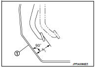
Check the height (H1) between the dash lower panel (1) and the
brake pedal upper surface.
H1 : Refer to BR-70, "Brake Pedal".
CAUTION:
Remove the floor trim.
Stop Lamp Switch
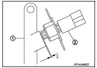
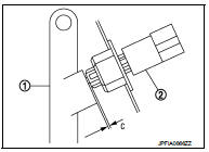
Check the clearance (C) among the brake pedal lever (1) and the
stop lamp switch (2) threaded end.
C : Refer to BR-70, "Brake Pedal".
CAUTION:
The stop lamp must turn off when the brake pedal is released.
NOTE:
Pull the brake pedal pad to make the clearance between the stop lamp switch threaded end and the brake peal lever.
Brake Switch/Brake Pedal Position Switch Check the clearance (C) among the brake pedal lever (1) and the brake switch/brake pedal position switch (2) threaded end.
C : Refer to BR-70, "Brake Pedal".
NOTE
:
Pull the brake pedal pad to make the clearance between the brake
switch/brake pedal position switch threaded end and the brake peal
lever.
Brake Pedal Play
Press the brake pedal. Check the brake pedal play (A) (stroke until
fluid pressure occurs).
A : Refer to BR-70, "Brake Pedal".
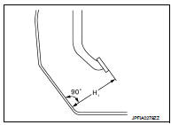
Depressed Brake Pedal Height Check the height between the dash lower panel (1) and the brake pedal upper surface (H2) when depressing the brake pedal at 490 N (50 kg, 110 lb) while turning engine ON.
H2 : Refer to BR-70, "Brake Pedal".
CAUTION: Remove the floor trim.
ADJUSTMENT
Brake Pedal Height
1. Remove instrument lower panel. Refer to IP-13, "Removal and Installation".
2. Disconnect the stop lamp switch and brake switch/brake pedal position switch harness connector.
3. Loosen the stop lamp switch and brake switch/brake pedal position switch 45° counterclockwise.
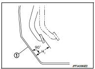
4. Loosen the lock nut (2) of input rod (1).
5. Rotate the input rod, adjust the brake pedal to the specified height (H1).
CAUTION:
The threaded end of the input rod must project to the inner
side (L) of the clevis (3).
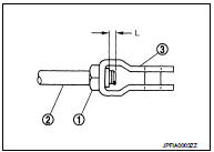
H1 : Refer to BR-70, "Brake Pedal".
6. Tighten the lock nut. Refer to BR-46, "Exploded View".
7. Adjust the clearance between the brake pedal lever and the stop lamp switch and brake switch/brake pedal position switch threaded end after adjusting the brake pedal height.
Stop Lamp Switch
1. Remove instrument lower panel. Refer to IP-13, "Removal and Installation".
2. Disconnect the harness connector from stop lamp switch.
3. Loosen the stop lamp switch 45° counterclockwise.
4. Press-fit the stop lamp switch (2) until the stop lamp switch hits the brake pedal lever (1) 45° clockwise while pulling the brake pedal pad slightly.
CAUTION:
• The clearance (C) between the brake pedal lever and stop
lamp switch threaded and must be the specified value.
C : Refer to BR-70, "Brake Pedal".
• The stop lamp must be turned off when the brake pedal is released.
Brake Switch/Brake Pedal Position Switch 1. Remove instrument lower panel. Refer to IP-13, "Removal and Installation".
2. Disconnect the harness connector from brake switch/brake pedal position switch.
3. Loosen the brake switch/brake pedal position switch 45° counterclockwise.
4. Press-fit the brake switch/brake pedal position switch (2) until the brake switch/brake pedal position switch hits the brake pedal lever (1) 45° clockwise while pulling the brake pedal pad slightly.
CAUTION:
The clearance (C) between the brake pedal lever and brake
switch/brake pedal position switch threaded and must be
the specified value.
C : Refer to BR-70, "Brake Pedal".
Depressed Brake Pedal Height 1. Perform the air bleeding. Refer to BR-13, "Bleeding Brake System".
2. Check the height between the dash lower panel (1) and the brake pedal upper surface (H2) when depressing the brake pedal at 490 N (50 kg, 110 lb) while turning engine ON.
H2 : Refer to BR-70, "Brake Pedal".
CAUTION:
Remove the floor trim.

 Brake fluid
Inspection
BRAKE FLUID LEVEL
• Check that the fluid level in the reservoir tank is within the specified
range (MAX – MIN lines).
• Visually check for any brake fluid leakage around the reservoir
...
Other materials:
P0300, P0301, P0302, P0303, P0304 misfire
DTC Logic
DTC DETECTION LOGIC
When a misfire occurs, engine speed will fluctuate. If the engine speed
fluctuates enough to cause the crankshaft
position (CKP) sensor (POS) signal to vary, ECM can determine that a misfire is
occurring.
The misfire detection logic consists of the following t ...
Service Equipment
RECOVERY/RECYCLING RECHARGING EQUIPMENT
Be certain to follow the manufacturer’s instructions for machine operation
and machine maintenance. Never
introduce any refrigerant other than that specified into the machine.
ELECTRICAL LEAK DETECTOR
Be certain to follow the manufacturer’s instruction ...
Fuel level sensor unit, fuel filter and fuel pump assembly
Exploded View
1. Fuel tank
2. Rock ring
3.
Fuel level sensor unit, fuel filter and
fuel pump assembly
4. O-ring
: Vehicle front
: Always replace after every
disassembly.
: N·m (kg-m, ft-lb)
1. Fuel filter and fuel pump assembly
2. Fuel gauge
Removal and Installation
WARNING:
...
