Nissan Juke Service and Repair Manual : Body construction
Body Construction (RHD Models)
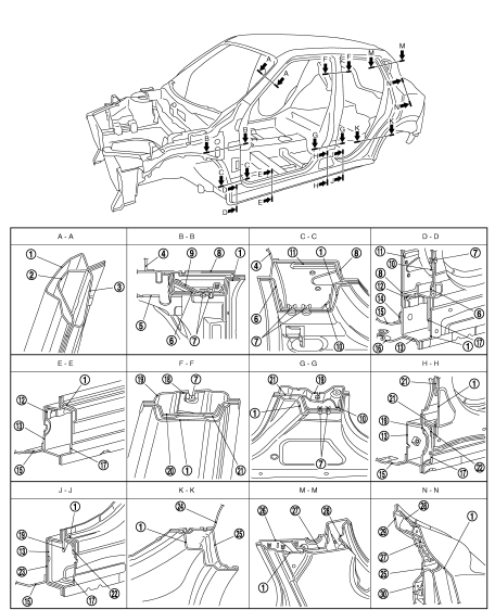
1. Outer side body
2. Outer front pillar reinforcement
3. Upper inner front pillar
4. Lower dash
5. Hoodledge reinforcement
6. Lower front pillar hinge brace
7. Weld nut
8. Side dash
9. Upper hinge plate
10. Lower hinge plate
11. Inner front pillar reinforcement
12. Inner front sill reinforcement
13. Inner sill
14. Front floor reinforcement
15. Front floor
16. Front outrigger
17. Outer sill reinforcement
18. Plate nut
19. Inner center pillar
20. Center pillar reinforcement
21. Center pillar hinge brace
22. Center sill reinforcement
23. Inner sill extension
24. Inner rear wheelhouse
25. Outer rear wheelhouse
26. Rear roof rail brace
27. Inner rear pillar reinforcement
28. Rear fender extension
29. Inner rear pillar
30. Inner rear wheelhouse reinforcement
Body Construction (LHD Models)
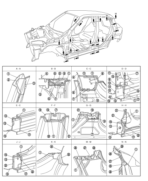
1. Outer side body
2. Outer front pillar reinforcement
3. Upper inner front pillar
4. Lower dash
5. Hoodledge reinforcement
6. Lower front pillar hinge brace
7. Weld nut
8. Side dash
9. Upper hinge plate
10. Lower hinge plate
11. Inner front pillar reinforcement
12. Inner front sill reinforcement
13. Inner sill
14. Front floor reinforcement
15. Front floor
16. Front outrigger
17. Outer sill reinforcement
18. Plate nut
19. Inner center pillar
20. Center pillar reinforcement
21. Center pillar hinge brace
22. Center sill reinforcement
23. Inner sill extension
24. Inner rear wheelhouse
25. Outer rear wheelhouse
26. Rear roof rail brace
27. Inner rear pillar reinforcement
28. Rear fender extension
29. Inner rear pillar
30. Inner rear wheelhouse reinforcement
31. Upper inner front pillar reinforcement
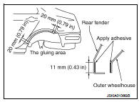
Rear Fender Hemming Process
1. A wheel arch is to be installed and hemmed over the left and right outer wheel houses.
2. In order to hem the wheel arch, it is necessary to repair any damaged or defaced parts around outer wheel house.
CAUTION:
Ensure that the area that is to be glued around the outer wheelhouse is
undamaged or defaced.
PROCEDURE OF THE HEMMING PROCESS
• Peel off old bonding material on the surface of the outer wheelhouse and clean thoroughly.
• Peel off a primer coat in the specified area where new adhesive is to be applied on rear fender (the replacing part).
• Apply new adhesive to both specified areas of the outer wheelhouse and rear fender.
<Adhesive> 3M™ Automix™ Panel Bonding Adhesive 08115 or equivalent
• Attach rear fender to the body of the car, and weld the required part except the hemming part.
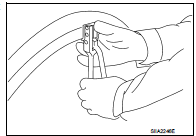
• Bend the welded part starting from the center of the wheel arch
gradually with a hammer and a dolly. (Also hem the end of the
flange.)
• Hemming with a hammer is conducted to an approximate angle of
80 degrees.
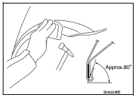
• Starting from the center, hem the wheel arch gradually, using slight back and forth motion with a hemming tool.
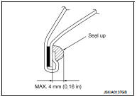
• Seal up the area around the hemmed end of the flange.
 Corrosion protection
Description
To provide improved corrosion prevention, the following anti-corrosive
measures have been implemented in
NISSAN production plants. When repairing or replacing body panels, it is
nece ...
 Replacement operations
Description
• This section is prepared for technicians who have attained a high level of
skill and experience in repairing
collision-damaged vehicles and also use modern service tools and equipmen ...
Other materials:
Compressor dose dot operate
Description
SYMPTOM
Compressor dose not operate.
Diagnosis Procedure
NOTE:
• Perform self-diagnosis with CONSULT-III before performing symptom diagnosis.
If any malfunction result or
DTC is detected, perform the corresponding diagnosis.
• Check that refrigerant is enclosed in cooler cycle n ...
Shift lock system
Component Function Check
1.CHECK SHIFT LOCK OPERATION (PART 1)
1. Turn ignition switch ON.
2. Shift the selector lever to “P” position.
3. Attempt to shift the selector lever to any other than position with the brake
pedal released.
Can the selector lever be shifted to any other position?
...
Back door request switch
Component Function Check
1.CHECK FUNCTION
1. Select “INTELLIGENT KEY” of “BCM” using CONSULT-III.
2. Select “REQ SW-BD/TR” in “DATA MONITOR” mode.
3. Check that the function operates normally according to the following
conditions.
Is the inspection result normal?
YES >> Back door req ...
