Nissan Juke Service and Repair Manual : Body alignment
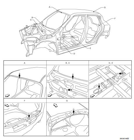
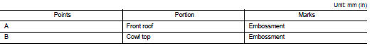
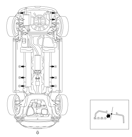
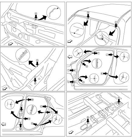
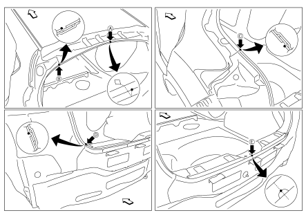
Body Center Marks (RHD Models)
A mark is placed on each part of the body to indicate the vehicle center. When repairing the vehicle frame (members, pillars, etc.) damaged by an accident which it enables more accurate and effective repair by using these marks together with body alignment specifications.
 : Vehicle front
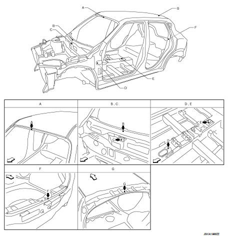
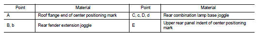
Body Center Marks (LHD Models)
A mark is placed on each part of the body to indicate the vehicle center. When repairing the vehicle frame (members, pillars, etc.) damaged by an accident which it enables more accurate and effective repair by using these marks together with body alignment specifications.
: Vehicle front
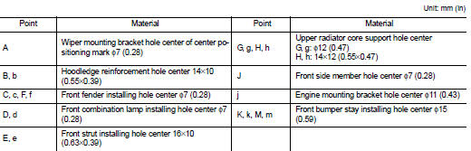
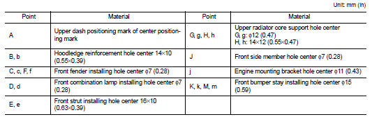
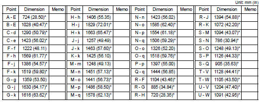
Description
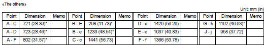
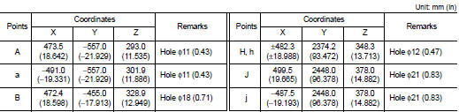
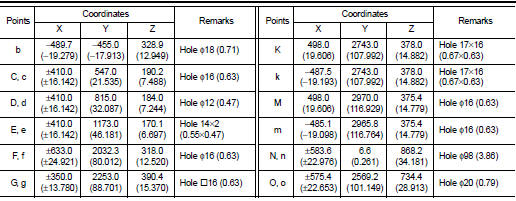
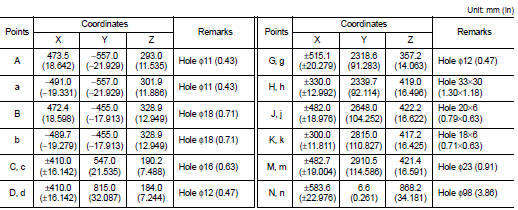
• All dimensions indicated in the figures are actual.
• When using a tracking gauge, adjust both pointers to equal length. Then check the pointers and gauge itself to make sure there is no free play.
• When a measuring tape is used, check to be sure there is no elongation, twisting or bending.
• Measurements should be taken at the center of the mounting holes.
• An asterisk (*) following the value at the measuring point indicates that the measuring point on the other side is symmetrically the same value.
• The coordinates of the measurement points are the distances measured from the standard line of ″X″, ″Y″ and ″Z″.
• ″Z″: Imaginary base line [200 mm (7.87 in) below datum line (″0Z″ at design plan)]
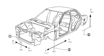
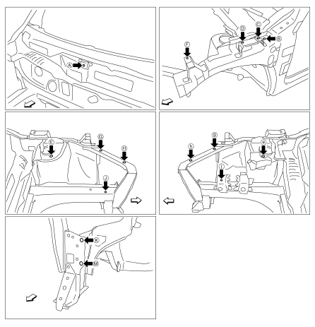
1. Vehicle center
2. Front axle center
3. Imaginary base line
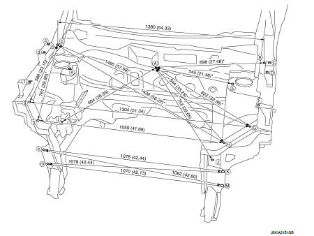
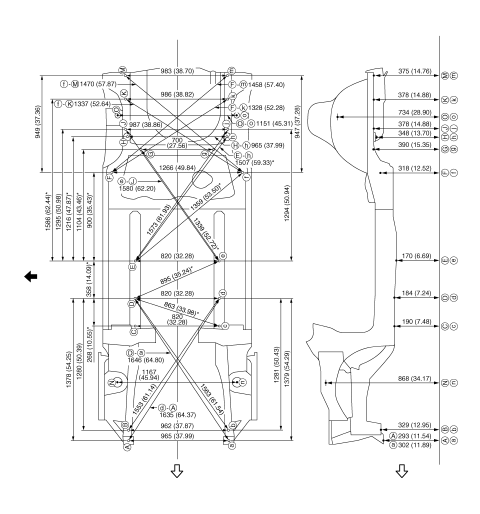
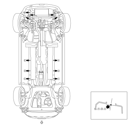
Engine Compartment (2WD RHD Models)
MEASUREMENT
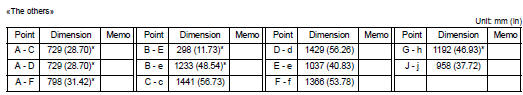
Dimensions marked with ″*″ indicate symmetrically identical dimensions on both the right and left hand of the vehicle.
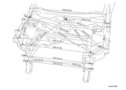
Unit: mm (in)
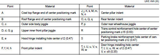
MEASUREMENT POINTS
 : Vehicle front
Engine Compartment (2WD LHD Models)
MEASUREMENT
Dimensions marked with ″*″ indicate symmetrically identical dimensions on both the right and left hand of the vehicle.
Unit: mm (in)
MEASUREMENT POINTS
 : Vehicle front
Engine Compartment (4WD RHD Models)
MEASUREMENT
Dimensions marked with ″*″ indicate symmetrically identical dimensions on both the right and left hand of the vehicle.
Unit: mm (in)
MEASUREMENT POINTS
 : Vehicle front
Engine Compartment (4WD LHD Models)
MEASUREMENT
Dimensions marked with ″*″ indicate symmetrically identical dimensions on both the right and left hand of the vehicle.
Unit: mm (in)
MEASUREMENT POINTS
 : Vehicle front
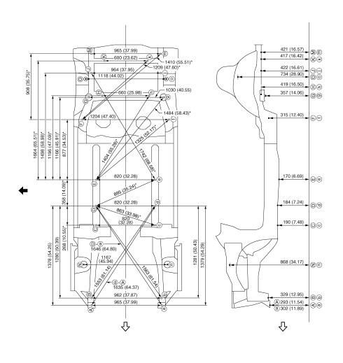
Underbody (2WD Models)
MEASUREMENT
Dimensions marked with ″*″ indicate symmetrically identical dimensions on both the right and left hand of the vehicle.
The following figure shows a bottom view and a side view of the vehicle.
Unit: mm (in)
 : Vehicle front
 : Vehicle left side
MEASUREMENT POINTS
 : Vehicle front
Underbody (4WD Models)
MEASUREMENT
Dimensions marked with ″*″ indicate symmetrically identical dimensions on both the right and left hand of the vehicle.
The following figure shows a bottom view and a side view of the vehicle.
Unit: mm (in)
: Vehicle front
 : Vehicle left side
MEASUREMENT POINTS
: Vehicle front
Passenger Compartment
MEASUREMENT
Dimensions marked with ″*″ indicate symmetrically identical dimensions on both the right and left hand of the vehicle.
Unit: mm (in)
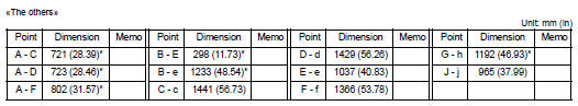
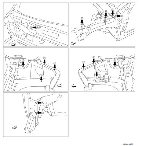
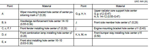
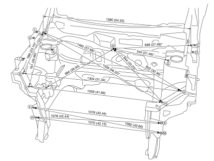
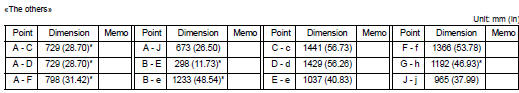
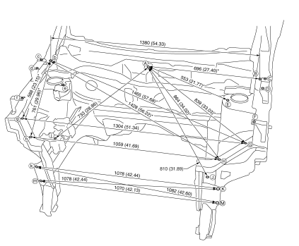
«The others»
MEASUREMENT POINTS
 : Vehicle front
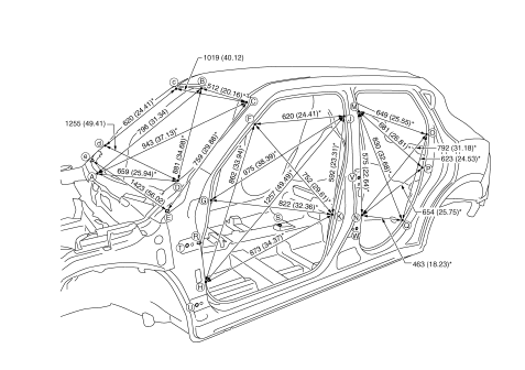
Rear Body
MEASUREMENT
Dimensions marked with ″*″ indicate symmetrically identical dimensions on both the right and left hand of the vehicle.
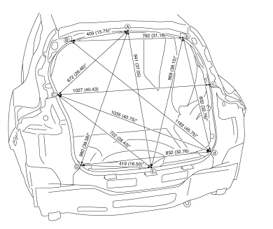
Unit: mm (in)
MEASUREMENT POINTS
 : Vehicle front

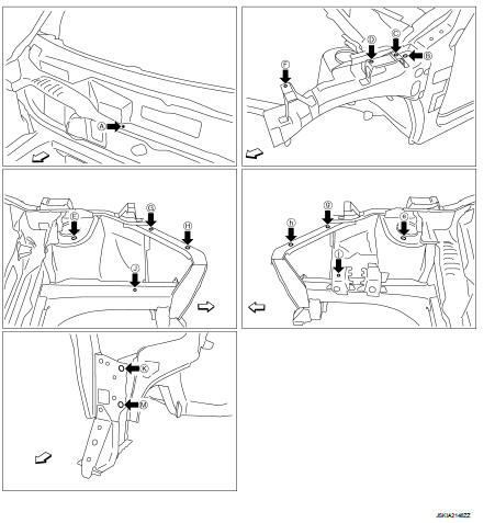
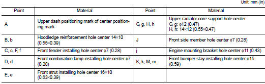
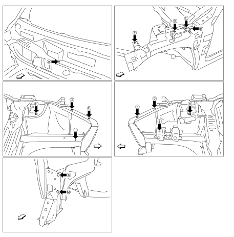
 Location of plastic parts
Precautions for Plastics
CAUTION:
• When repairing and painting a portion of the body adjacent to plastic parts,
consider their characteristics (influence of heat
and solvent) and remove them i ...
Other materials:
Main line between ipdm-e and dlc circuit
Diagnosis Procedure
1.CHECK CONNECTOR
1. Turn the ignition switch OFF.
2. Disconnect the battery cable from the negative terminal.
3. Check the following terminals and connectors for damage, bend and loose
connection (connector side
and harness side).
- Harness connector E105
- Harness co ...
A/C indicator
Diagnosis Procedure
1.CHECK SYMPTOM
Check symptom.
A/C indicator dose not turn ON>>GO TO 2.
A/C indicator dose not turn OFF>>GO TO 6.
2.CHECK FUSE
1. Turn ignition switch OFF.
2. Check 10A fuse (No. 15, located in fuse block (J/B)].
NOTE:
Refer to PG-22, "Fuse, Conn ...
B terminal circuit
Description
“B” terminal circuit supplies power to charge the battery and to operate the
vehicle’s electrical system.
Diagnosis Procedure
1.CHECK “B” TERMINAL CONNECTION
1. Turn ignition switch OFF.
2. Check if “B” terminal is clean and tight.
Is the inspection result normal?
YES >> ...
