Nissan Juke Service and Repair Manual : Blower motor
Diagnosis Procedure
1.CHECK SYMPTOM
Check symptom (A or B).
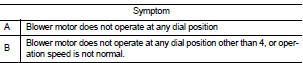
Which symptom is detected? A >>GO TO 2.
B >>GO TO 7.
2.CHECK FUSE
1. Turn ignition switch OFF.
2. Check 15A fuses (Nos. 14 and 16, located in fuse block (J/B)].
NOTE
:
Refer to PG-22, "Fuse, Connector and Terminal Arrangement".
Is the inspection result normal? YES >> GO TO 3.
NO >> Replace the blown fuse after repairing the affected circuit if a fuse is blown.
3.CHECK BLOWER MOTOR POWER SUPPLY
1. Disconnect blower motor connector.
2. Turn ignition switch ON.
3. Check voltage between blower motor harness connector and ground.
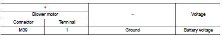
Is the inspection result normal? YES >> GO TO 5.
NO >> GO TO 4.
4.CHECK BLOWER RELAY
1. Turn ignition switch OFF.
2. Check blower relay. Refer to HAC-230, "Component Inspection (Blower Relay)".
Is the inspection result normal? YES >> Repair harness or connector between blower motor and fuse.
NO >> Replace blower relay.
5.CHECK FAN SWITCH GROUND CIRCUIT FOR OPEN
1. Turn ignition switch OFF.
2. Disconnect A/C control connector.
3. Check continuity between A/C control harness connector and ground.
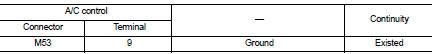
Is the inspection result normal?
YES >> GO TO 6.
NO >> Repair harness or connector.
6.CHECK FAN SWITCH 4 POSITION CIRCUIT FOR OPEN Check continuity between A/C control harness connector and blower motor harness connector.
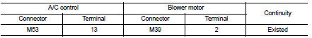
Is the inspection result normal? YES >> GO TO 10.
NO >> Repair the harness or connector.
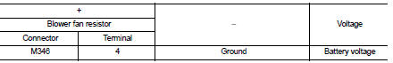
7.CHECK BLOWER FAN RESISTOR POWER SUPPLY
1. Turn ignition switch OFF.
2. Disconnect blower fan resistor connector.
3. Turn ignition switch ON.
4. Check voltage between blower fan resistor harness connector and ground.
Is the inspection result normal? YES >> GO TO 8.
NO >> Repair harness or connector between blower fan resistor and blower motor.
8.CHECK BLOWER FAN RESISTOR
1. Turn the ignition switch OFF.
2. Check blower fan resistor. Refer to HAC-230, "Component Inspection (Blower Fan Resistor)".
Is the inspection result normal? YES >> GO TO 9.
NO >> Replace blower fan resistor. Refer to HAC-242, "Removal and Installation".
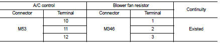
9.CHECK FAN SWITCH 1, 2, 3 POSITION CIRCUIT FOR OPEN
Check continuity between A/C control harness connector and blower fan resistor.
Is the inspection result normal? YES >> GO TO 10.
NO >> Repair harness or connector.
10.CHECK FAN SWITCH
Check fan switch. Refer to HAC-231, "Component Inspection (Fan Switch)".
Is the inspection result normal? YES >> Replace blower motor. Refer to VTL-15, "Removal and Installation (LHD models)" or VTL-16, "Removal and Installation (RHD models)".
NO >> Replace A/C control. Refer to HAC-239, "Removal and Installation".
Component Inspection (Blower Motor)
1.CHECK BLOWER MOTOR
1. Remove blower motor. Refer to VTL-15, "Removal and Installation (LHD models)" or VTL-16, "Removal and Installation (RHD models)".
2. Check that there is not any mixing foreign object in the blower motor.
Is the inspection result normal? YES >> GO TO 2.
NO >> Replace blower motor. Refer to VTL-15, "Removal and Installation (LHD models)" or VTL-16, "Removal and Installation (RHD models)".
2.CHECK BLOWER MOTOR
Check that there is not breakage or damage in the blower motor.
Is the inspection result normal? YES >> GO TO 3.
NO >> Replace blower motor. Refer to VTL-15, "Removal and Installation (LHD models)" or VTL-16, "Removal and Installation (RHD models)".
3.CHECK BLOWER MOTOR
Check that blower motor turns smoothly.
Is the inspection result normal? YES >> INSPECTION END
NO >> Replace blower motor. Refer to VTL-15, "Removal and Installation (LHD models)" or VTL-16, "Removal and Installation (RHD models)".
Component Inspection (Blower Relay)
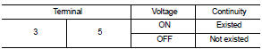
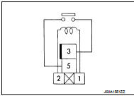
1.CHECK BLOWER RELAY
1. Remove blower relay. Refer to PG-22, "Fuse, Connector and Terminal Arrangement".
2. Check continuity between blower relay terminal 3 and 5 when the voltage is supplied between terminal 1 and 2.
Is the inspection result normal? YES >> INSPECTION END
NO >> Replace blower relay.
Component Inspection (Blower Fan Resistor)
1.CHECK BLOWER FAN RESISTOR
1. Disconnect blower fan resistor connector.
2. Check resistance between blower fan resistor terminals. Refer to applicable table for the normal value.
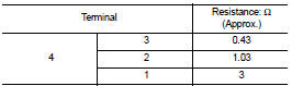
Is the inspection result normal? YES >> INSPECTION END
NO >> Replace blower fan resistor. Refer to HAC-242, "Removal and Installation".
Component Inspection (Fan Switch)
1.CHECK FAN SWITCH
Check continuity between A/C control terminals.
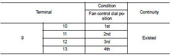
Is the inspection result normal? YES >> INSPECTION END
NO >> Replace A/C control. Refer to HAC-239, "Removal and Installation".
 A/C indicator
Diagnosis Procedure
1.CHECK SYMPTOM
Check symptom.
A/C indicator dose not turn ON>>GO TO 2.
A/C indicator dose not turn OFF>>GO TO 6.
2.CHECK FUSE
1. Turn ignition switch OFF.
...
 Magnet clutch
Component Function Check
1.CHECK MAGNET CLUTCH OPERATION
Perform auto active test of IPDM E/R. Refer to PCS-12, "Diagnosis
Description" (with Intelligent Key) or PCS-
43, "Diagnosi ...
Other materials:
Operating tips
• When the shift lever is shifted to the R (Reverse) position, the monitor screen
automatically changes to the RearView Monitor mode. However, the radio can be heard.
• When the view is switched, the display images on the screen may be displayed with
some delay.
• When the temperature is extre ...
Engine control system
Engine control system : Component Parts Location
ENGINE ROOM COMPARTMENT
1. Boost control actuator
2. Turbocharger boost control solenoid
valve
3. A/F sensor 1
4. Recirculation valve
5. EVAP canister purge volume control
solenoid valve
6. Inter cooler
7. Refrigerant pressure sensor
R ...
C1111 ABS motor, motor relay system
DTC Logic
DTC DETECTION LOGIC
DTC CONFIRMATION PROCEDURE
1.PRECONDITIONING
If “DTC CONFIRMATION PROCEDURE” has been previously conducted, always turn
ignition switch OFF and
wait at least 10 seconds before conducting the next test.
>> GO TO 2.
2.CHECK DTC DETECTION
With CONSULT ...
