Nissan Juke Service and Repair Manual : Blower motor
Diagnosis Procedure
1.CHECK SYMPTOM
Check symptom (A, B or C).
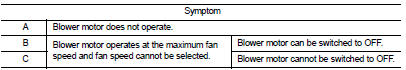
Which symptom is detected? A >>GO TO 2.
B >>GO TO 11.
C >> GO TO 13.
2.CHECK FUSE
1. Turn ignition switch OFF.
2. Check following fuses.
- 10A fuse [No. 15, located in fuse block (J/B)] - 15A fuses [Nos. 14 and 16, located in the fuse block (J/B)]
NOTE
:
Refer to PG-22, "Fuse, Connector and Terminal Arrangement".
Is the inspection result normal? YES >> GO TO 3.
NO >> Replace the blown fuse after repairing the affected circuit if a fuse is blown.
3.CHECK BLOWER MOTOR POWER SUPPLY
1. Disconnect blower motor connector.
2. Turn ignition switch ON.
3. Check voltage between blower motor harness connector and ground.
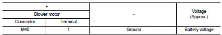
Is the inspection result normal? YES >> GO TO 5.
NO >> GO TO 4.
4.CHECK BLOWER RELAY
1. Turn ignition switch OFF.
2. Check blower relay. Refer to HAC-173, "Component Inspection (Blower Relay)".
Is the inspection result normal? YES >> Repair harness or connector between blower motor and fuse.
NO >> Replace blower relay.
5.CHECK FAN CONTROL AMP. POWER SUPPLY (SOURCE) CIRCUIT
1. Turn ignition switch OFF.
2. Connect blower motor connector.
3. Disconnect fan control amp. connector.
4. Turn ignition switch ON.
5. Check voltage between fan control amp. harness connector and ground.
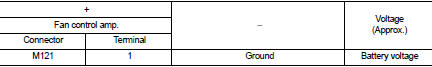
Is the inspection result normal? YES >> GO TO 7.
NO >> GO TO 6.
6.CHECK FAN CONTROL AMP. POWER SUPPLY (SOURCE) CIRCUIT FOR OPEN
1. Turn ignition switch OFF.
2. Disconnect blower motor connector.
3. Check continuity between fan control amp. harness connector and blower motor harness connector.
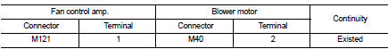
Is the inspection result normal? YES >> Replace blower motor. Refer to VTL-15, "Removal and Installation (LHD models)" or VTL-16, "Removal and Installation (RHD models)".
NO >> Repair harness or connector.
7.CHECK FAN CONTROL AMP. GROUND (DRAIN) CIRCUIT FOR OPEN
1. Turn ignition switch OFF.
2. Check continuity between fan control amp. harness connector and ground.
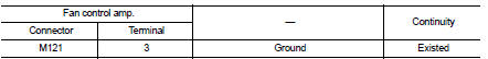
Is the inspection result normal? YES >> GO TO 8.
NO >> Repair harness or connector.
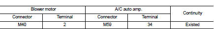
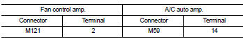
8.CHECK FAN CONTROL AMP. CONTROL SIGNAL (GATE) CIRCUIT FOR OPEN
1. Disconnect A/C auto amp. connector.
2. Check continuity between fan control amp. harness connector and A/C auto amp. harness connector.
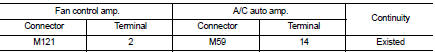
Is the inspection result normal? YES >> GO TO 9.
NO >> Repair harness or connector.
9.CHECK FAN CONTROL AMP. CONTROL SIGNAL (GATE) CIRCUIT FOR SHORT
Check continuity between fan control amp. harness connector and ground.
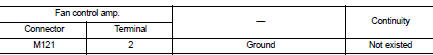
Is the inspection result normal? YES >> GO TO 10.
NO >> Repair harness or connector.
10.CHECK FAN CONTROL AMP.
Check fan control amp. Refer to HAC-173, "Component Inspection (Fan Control Amp.)".
Is the inspection result normal? YES >> Replace A/C auto amp. Refer to HAC-188, "Removal and Installation".
NO >> Replace fan control amp. Refer to HAC-194, "Removal and Installation".
11.CHECK A/C AUTO AMP. IGNITION POWER SUPPLY FEEDBACK SIGNAL
1. Turn ignition switch ON.
2. Check voltage between A/C auto amp. harness connector and ground.
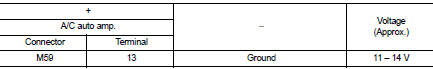
Is the inspection result normal? YES >> GO TO 12.
NO >> Repair harness or connector between A/C auto amp. and fuse.
12.CHECK BLOWER MOTOR FEEDBACK SIGNAL CIRCUIT FOR OPEN
1. Turn ignition switch OFF.
2. Disconnect blower motor connector and A/C auto amp. connector.
3. Check continuity between blower motor harness connector and A/C auto amp. harness connector.
Is the inspection result normal? YES >> Replace A/C auto amp. Refer to HAC-188, "Removal and Installation".
NO >> Repair harness or connector.
13.CHECK BLOWER MOTOR FEEDBACK SIGNAL CIRCUIT AND FAN CONTROL AMP. POWER SUPPLY (SOURCE) CIRCUIT FOR SHORT
1. Turn ignition switch OFF.
2. Disconnect following connectors.
- Blower fan motor
- Fan control amp.
- A/C auto amp.
3. Check continuity between blower motor harness connector and ground.
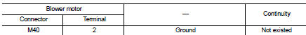
Is the inspection result normal? YES >> GO TO 14.
NO >> Repair harness or connector.
14.CHECK FAN CONTROL AMP. CONTROL SIGNAL (GATE) CIRCUIT FOR SHORT TO POWER SUPPLY
Check harness between fan control amp. harness connector and A/C auto amp. harness connector for short to power supply.
Is the inspection result normal? YES >> GO TO 10.
NO >> Repair harness or connector.
Component Inspection (Blower Motor)
1.CHECK BLOWER MOTOR
1. Remove blower motor. Refer to VTL-15, "Removal and Installation (LHD models)" or VTL-16, "Removal and Installation (RHD models)".
2. Check that there is not any mixing foreign object in the blower motor.
Is the inspection result normal? YES >> GO TO 2.
NO >> Replace blower motor. Refer to VTL-15, "Removal and Installation (LHD models)" or VTL-16, "Removal and Installation (RHD models)".
2.CHECK BLOWER MOTOR
Check that there is not breakage or damage in the blower motor.
Is the inspection result normal? YES >> GO TO 3.
NO >> Replace blower motor. Refer to VTL-15, "Removal and Installation (LHD models)" or VTL-16, "Removal and Installation (RHD models)".
3.CHECK BLOWER MOTOR
Check that blower motor turns smoothly.
Is the inspection result normal? YES >> INSPECTION END
NO >> Replace blower motor. Refer to VTL-15, "Removal and Installation (LHD models)" or VTL-16, "Removal and Installation (RHD models)".
Component Inspection (Blower Relay)
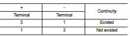
1.CHECK BLOWER RELAY
1. Remove blower relay. Refer to PG-22, "Fuse, Connector and Terminal Arrangement".
2. Check continuity between blower relay terminal 3 and 5 when the voltage is supplied between terminal 1 and 2.
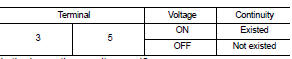
Is the inspection result normal? YES >> INSPECTION END
NO >> Replace blower relay.
Component Inspection (Fan Control Amp.)
1.CHECK FAN CONTROL AMP.
1. Remove fan control amp. Refer to HAC-194, "Removal and Installation".
2. Check continuity between fan control amp. terminals.
Is the inspection result normal? YES >> INSPECTION END
NO >> Replace fan control amp. Refer to HAC-194, "Removal and Installation".
 Blower fan on signal
Component Function Check
1.CHECK BLOWER FAN ON SIGNAL
With CONSULT-III
1. Turn ignition switch ON.
2. Select “AIR CONDITIONER” of “BCM” using CONSULT-III.
3. Select “FAN ON SIG” in “DATA MONITOR” ...
 Magnet clutch
Component Function Check
1.CHECK MAGNET CLUTCH OPERATION
Perform auto active test of IPDM E/R. Refer to PCS-12, "Diagnosis
Description" (with Intelligent Key) or PCS-
43, "Diagnosi ...
Other materials:
Power supply and ground circuit
Combination meter
COMBINATION METER : Diagnosis Procedure
1.CHECK FUSE
Check for blown fuses.
Is the inspection result normal?
YES >> GO TO 2.
NO >> Be sure to eliminate cause of malfunction before installing new fuse.
2.CHECK POWER SUPPLY CIRCUIT
Check voltage between comb ...
Front wheel hub and knuckle
Inspection
COMPONENT PART
Check that the mounting conditions (looseness, backlash) of each component
and component conditions
(wear, damage) are normal.
WHEEL HUB ASSEMBLY (BEARING-INTEGRATED TYPE)
Check the following items, and replace the part if necessary.
• Move wheel hub assembly in ...
Key ID warning does not operate
Diagnosis Procedure
1.CHECK DTC WITH BCM AND COMBINATION METER
Check that DTC is not detected with BCM and combination meter.
Is the inspection result normal?
YES >> GO TO 2.
NO-1 >> Refer to BCS-67, "DTC Index". (BCM)
NO-2 >> Refer to MWI-36, "DTC Index&qu ...
