Nissan Juke Service and Repair Manual : Blower fan on signal
Component Function Check
1.CHECK BLOWER FAN ON SIGNAL
 With CONSULT-III
1. Turn ignition switch ON.
2. Select “AIR CONDITIONER” of “BCM” using CONSULT-III.
3. Select “FAN ON SIG” in “DATA MONITOR” mode, and check status under the following condition.
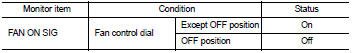
Is the inspection result normal? YES >> INSPECTION END
NO >> Refer to HAC-222, "Diagnosis Procedure".
Diagnosis Procedure
1.CHECK FAN SWITCH POWER SUPPLY SIGNAL
1. Turn ignition switch OFF.
2. Disconnect A/C control harness connector.
3. Turn ignition switch ON.
4. Check output waveform between A/C control and ground with using oscilloscope.
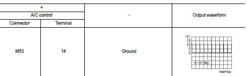
Is the inspection result normal? YES >> Replace A/C control. Refer to HAC-239, "Removal and Installation".
NO >> GO TO 2.
2.CHECK BLOWER FAN ON SIGNAL CIRCUIT FOR OPEN
1. Turn ignition switch OFF.
2. Disconnect BCM connector.
3. Check continuity A/C control harness connector and BCM harness connector.

Is the inspection result normal? YES >> GO TO 3.
NO >> Repair harness or connector.
3.CHECK BLOWER FAN ON SIGNAL CIRCUIT FOR SHORT
Check continuity between A/C control harness connector and ground.
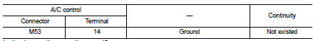
Is the inspection result normal? YES >> Replace BCM. Refer to BCS-93, "Removal and Installation" (with Intelligent Key) or BCS-161, "Removal and Installation" (without Intelligent Key).
NO >> Repair harness or connector.
 A/C switch
Component Function Check
1.CHECK A/C ON SIGNAL
With CONSULT-III
1. Turn ignition switch ON.
2. Select “AIR CONDITIONER” of “BCM” using CONSULT-III.
3. Select “AIR COND SW” in “DATA MONITOR” mode, ...
 Thermo control amplifier
Component Function Check
1.CHECK A/C ON SIGNAL
With CONSULT-III
1. Turn ignition switch ON.
2. Select “AIR CONDITIONER” of “BCM” using CONSULT-III.
3. Select “THERMO AMP” in “DATA MONITOR” mode, ...
Other materials:
Electric power steering system
WARNING
• If the engine is not running or is turned off while driving, the power assist
for the steering will not work.
Steering will be harder to operate.
• When the electric power steering warning light illuminates with the engine
running, the power assist for the steering will cease ...
Wiring diagram
IPDM E/R
Wiring Diagram
For connector terminal arrangements, harness layouts, and alphabets in a
(option abbreviation; if not
described in wiring diagram), refer to GI-12, "Connector Information/Explanation
of Option Abbreviation".
...
System
NISSAN dynamic control system
NISSAN DYNAMIC CONTROL SYSTEM : System Description
SYSTEM DIAGRAM
• *1: M/T models except for K9K engine models
• *2: CVT models
MULTI DISPLAY UNIT INPUT/OUTPUT SINGNAL
Output signal
SYSTEM DESCRIPTION
• The multi display unit receives necessary informatio ...
