Nissan Juke Service and Repair Manual : BCM, ECM, IPDM E/R
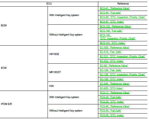
List of ECU Reference
 PTC heater control unit
Reference Value
CONSULT-III DATA MONITOR REFERENCE VALUES
TERMINAL LAYOUT
PHYSICAL VALUES
DTC Index
...
 Wiring diagram
MANUAL AIR CONDITIONING SYSTEM
Wiring Diagram
For connector terminal arrangements, harness layouts, and alphabets in a
(option abbreviation; if not
described in wiring diagram), refer to GI-12, &q ...
Other materials:
Removal and Installation Procedure for CVT Unit Connector
REMOVAL
Rotate bayonet ring (1) counterclockwise, pull out CVT unit harness
connector (2) upward and remove it.
INSTALLATION
1. Align Δ marking on CVT unit harness connector terminal body
with marking on bayonet ring, insert CVT unit harness connector,
and then rotate bayonet ...
Air cleaner and air duct
Exploded View
1. Hose clamp
2. PCV hose
3. Hose clamp
4. Air cleaner filter
5. Air cleaner filter case
6. Grommet
7. Inlet air duct (lower)
8. Grommet
9. Inlet air duct (upper)
10. Bracket
11. Air cleaner case
12. O-ring
13. Mass air flow sensor
14. Air duct
A. To electric ...
Front drive shaft boot
Exploded View
LEFT SIDE
1. Circular clip
2. Dust shield
3. Housing assembly
4. Boot band
5. Boot
6. Damper band
7. Dynamic damper
8. Circular clip
9. Joint sub-assembly
: Wheel side
: Fill NISSAN Genuine grease or
equivalent.
: Always replace after every
disassembly.
RIGHT ...
