Nissan Juke Service and Repair Manual : Basic inspection
DIAGNOSIS AND REPAIR WORKFLOW (METER SYSTEM)
Work flow
OVERALL SEQUENCE
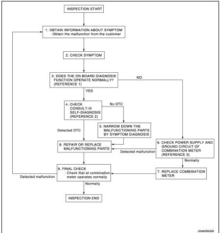
• Reference 1···MWI-22, "On Board Diagnosis Function".
• Reference 2···MWI-36, "DTC Index".
• Reference 3···MWI-51, "COMBINATION METER : Diagnosis Procedure".
DETAILED FLOW
1.OBTAIN INFORMATION ABOUT SYMPTOM
Interview the customer to obtain as much information as possible about the conditions and environment under which the malfunction occurred.
>> GO TO 2.
2.CHECK SYMPTOM
• Check the symptom based on the information obtained from the customer.
• Check that any other malfunctions are present.
>> GO TO 3.
3.CHECK ON BOARD DIAGNOSIS OPERATION
Check that the on board diagnosis function operates. Refer to MWI-22, "On Board Diagnosis Function".
Does the on board diagnosis function operate normally? YES >> GO TO 4.
NO >> GO TO 6.
4.CHECK CONSULT-III SELF-DIAGNOSIS RESULTS
Connect CONSULT-III and perform self-diagnosis. Refer to MWI-36, "DTC Index".
Are self-diagnosis results normal? YES >> GO TO 5.
NO >> GO TO 8.
5.NARROW DOWN THE MALFUNCTIONING PARTS BY SYMPTOM DIAGNOSIS
Perform symptom diagnosis and narrow down the malfunctioning parts.
>> GO TO 8.
6.CHECK COMBINATION METER POWER SUPPLY AND GROUND CIRCUITS
Check combination meter power supply and ground circuits. Refer to MWI-51, "COMBINATION METER : Diagnosis Procedure".
Is inspection result OK? YES >> GO TO 7.
NO >> GO TO 8.
7.REPLACE COMBINATION METER
Replace combination meter.
>> GO TO 9.
8.REPAIR OR REPLACE MALFUNCTIONING PARTS
Repair or replace the malfunctioning parts.
NOTE
:
If DTC is displayed, erase DTC after repair or replace malfunctioning parts.
>> GO TO 9.
9.FINAL CHECK
Check that the combination meter operates normally.
Do they operate normally? YES >> INSPECTION END
NO >> GO TO 1.
 Wiring diagram
METER SYSTEM
Wiring Diagram
For connector terminal arrangements, harness layouts, and alphabets in a
(option abbreviation; if not
described in wiring diagram), refer to GI-12, "Connector Info ...

Other materials:
System
Engine control system : System Diagram
Engine control system : System Description
ECM performs various controls such as fuel injection control and ignition
timing control.
MULTIPORT FUEL INJECTION SYSTEM
Multiport fuel injection system : System Diagram
Multiport fuel injection system : ...
Commercial Service Tools
CAUTION:
• Every time the vehicle is lifted up, maintain the complete vehicle curb
condition.
• Since the vehicle's center of gravity changes when removing main parts on the
front side (engine,
transmission, suspension etc.), support a jack up point on the rear side garage
jack with a mis ...
Power transistor
Exploded View
1. A/C unit assembly
2. Blower fan resistor*1
3. Sub harness*1
4. Power transistor*2
5. Sub harness*2
6. Blower motor
• *1: Manual air conditioner
• *2: Automatic air conditioner
Removal and Installation
REMOVAL
1. Remove instrument panel assembly. Refer to IP-13, &quo ...
