Nissan Juke Service and Repair Manual : Basic inspection
Diagnosis and repair workflow
Trouble Diagnosis Flow Chart
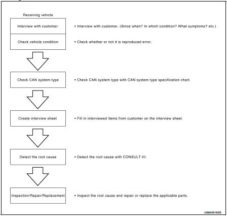
Trouble Diagnosis Procedure
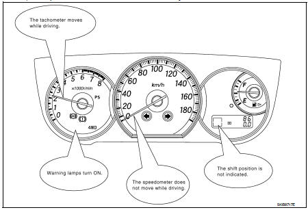
INTERVIEW WITH CUSTOMER
Interview with the customer is important to detect the root cause of CAN communication system errors and to understand vehicle condition and symptoms for proper trouble diagnosis.
Points in interview
• What: Parts name, system name
• When: Date, Frequency
• Where: Road condition, Place
• In what condition: Driving condition/environment
• Result: Symptom
Notes for checking error symptoms: • Check normal units as well as error symptoms.
• Check normal units as well as error symptoms.
- Example: Circuit between ECM and the combination meter is judged normal if the customer indicates tachometer functions normally.
• When a CAN communication system error is present, multiple control units may malfunction or go into failsafe mode.
• Indication of the combination meter is important to detect the root cause because it is the most obvious to the customer, and it performs CAN communication with many units.
INSPECTION OF VEHICLE CONDITION
Check whether the symptom is reproduced or not.
NOTE
:
Do not turn the ignition switch OFF or disconnect the battery cable while
reproducing the error. The error may
temporarily correct itself, making it difficult to determine the root cause.
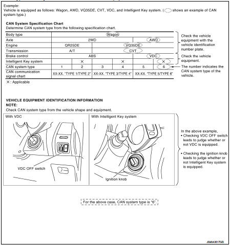
CHECK OF CAN SYSTEM TYPE (HOW TO USE CAN SYSTEM TYPE SPECIFICATION CHART)
Determine CAN system type based on vehicle equipment.
NOTE
:
• This chart is used if CONSULT-III does not automatically recognize CAN system
type.
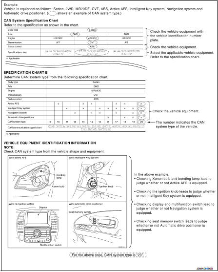
• There are two styles for CAN system type specification charts. Depending on the number of available system types, either style A or style B may be used.
CAN System Type Specification Chart (Style A) NOTE
: CAN system type is easily checked with the vehicle equipment identification information shown in the chart.
CAN System Type Specification Chart (Style B)
NOTE
: CAN system type is easily checked with the vehicle equipment identification information shown in the chart.
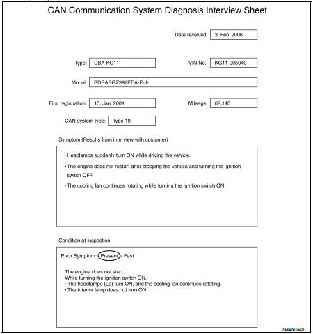
CREATE INTERVIEW SHEET
Fill out the symptom described by the customer, vehicle condition, and CAN system type on the interview sheet.
Interview Sheet (Example)
DETECT THE ROOT CAUSE
CAN diagnosis function of CONSULT-III detects the root cause.
 Trouble diagnosis
System Diagram
Condition of Error Detection
DTC (e.g. U1000 and U1001) of CAN communication is indicated on SELF-DIAG
RESULTS on CONSULT-III
if a CAN communication signal is not transmitted o ...
 LAN system can
...
Other materials:
How to select piston and bearing
Description
• The identification grade stamped on each part is the grade for the
dimension measured in new condition. This grade cannot apply to reused parts.
• For reused or repaired parts, measure the dimension accurately. Determine the
grade by comparing the
measurement with the values o ...
Audio system symptoms
Models with USB connection function
MODELS WITH USB CONNECTION FUNCTION : Symptom Table
AUDIO SYSTEM
RELATED TO HANDS-FREE PHONE
• Check that the cellular phone is the corresponding type (Bluetooth™
enabled) and Bluetooth™ turns ON.
• Malfunction may occur due to the version change of the p ...
Removal and Installation Procedure for CVT Unit Connector
REMOVAL
• Rotate bayonet ring (A) counterclockwise. Pull out CVT unit harness
connector (B) upward and remove it.
INSTALLATION
1. Align marking (A) on CVT unit harness connector terminal with
marking (B) on bayonet ring. Insert CVT unit harness connector.
2. Rotate bayonet ring clockwise.
...
