Nissan Juke Service and Repair Manual : Basic inspection
Inspection and adjustment
Additional service when replacing control unit (BCM
)
ADDITIONAL SERVICE WHEN REPLACING CONTROL UNIT (BCM) : Description
BEFORE REPLACEMENT
When replacing BCM, save or print current vehicle specification with CONSULT-III configuration before replacement.
NOTE
:
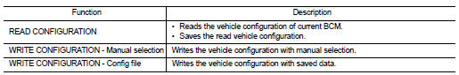
If “READ CONFIGURATION” can not be used, use the “WRITE CONFIGURATION - Manual
selection” after
replacing BCM.
AFTER REPLACEMENT
CAUTION:
• When replacing BCM, you must perform “WRITE CONFIGURATION” with CONSULT-III.
- Complete the procedure of “WRITE CONFIGURATION” in order.
- If you set incorrect “WRITE CONFIGURATION”, incidents might occur.
- Configuration is different for each vehicle model. Confirm configuration of each vehicle model.
• When replacing BCM, perform the system initialization (NATS).
ADDITIONAL SERVICE WHEN REPLACING CONTROL UNIT (BCM) : Special Repair Requirement
1.SAVING VEHICLE SPECIFICATION
 CONSULT-III Configuration
Perform “READ CONFIGURATION” to save or print current vehicle specification. Refer to BCS-80, "CONFIGURATION (BCM) : Description".
NOTE
:
If “READ CONFIGURATION” can not be used, use the “WRITE CONFIGURATION - Manual
selection” after
replacing BCM.
>> GO TO 2.
2.REPLACE BCM
Replace BCM. Refer to BCS-93, "Removal and Installation".
>> GO TO 3.
3.WRITING VEHICLE SPECIFICATION
 CONSULT-III Configuration
Perform “WRITE CONFIGURATION - Config file” or “WRITE CONFIGURATION - Manual selection” to write vehicle specification. Refer to BCS-81, "CONFIGURATION (BCM) : Special Repair Requirement".
>> GO TO 4.
4.INITIALIZE BCM (NATS)
Perform BCM initialization. (NATS) >> WORK END
Configuration (BCM)
CONFIGURATION (BCM) : Description
Vehicle specification needs to be written with CONSULT-III because it is not written after replacing BCM.
Configuration has three functions as follows
CAUTION:
• When replacing BCM, you must perform “WRITE CONFIGURATION” with CONSULT-III.
• Complete the procedure of “WRITE CONFIGURATION” in order.
• If you set incorrect “WRITE CONFIGURATION”, incidents might occur.
• Configuration is different for each vehicle model. Confirm configuration of each vehicle model.
• Never perform “WRITE CONFIGURATION” except for new BCM.
CONFIGURATION (BCM) : Special Repair Requirement
1.WRITING MODE SELECTION
 CONSULT-III Configuration
Select “CONFIGURATION” of BCM.
When writing saved data>>GO TO 2.
When writing manually>>GO TO 3.
2.PERFORM “WRITE CONFIGURATION - CONFIG FILE”
 CONSULT-III Configuration
Perform “WRITE CONFIGURATION - Config file”.
>> WORK END 3.PERFORM “WRITE CONFIGURATION - MANUAL SELECTION”
 CONSULT-III Configuration
1. Select "WRITE CONFIGURATION - Manual selection".
2. Identify the correct model and configuration list. Refer to BCS-81, "CONFIGURATION (BCM) : Configuration list".
3. Confirm and/or change setting value for each item.
CAUTION:
Thoroughly read and understand the vehicle specification. Incorrect settings may
result in abnormal
control of ECU.
4. Select "SETTING".
CAUTION:
Make sure to select “SETTING” even if the indicated configuration of brand new
BCM is same as
the desirable configuration. If not, configuration which is set automatically by
selecting vehicle
model can not be memorized.
5. When "COMMAND FINISHED", select "END".
>> GO TO 4.
4.OPERATION CHECK
Confirm that each function controlled by BCM operates normally.
>> WORK END
CONFIGURATION (BCM) : Configuration list
CAUTION:
Thoroughly read and understand the vehicle specification. Incorrect settings may
result in abnormal
control of ECU.
2WD MODELS
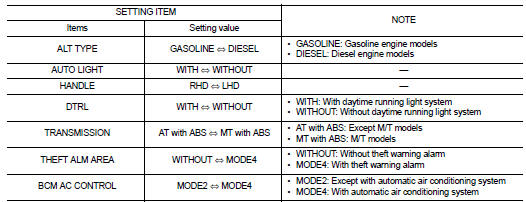
⇔: Items which confirm vehicle specifications 4WD MODELS
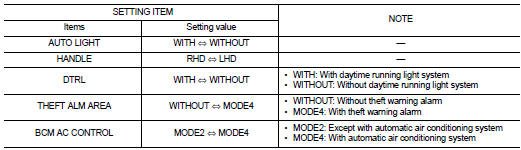
⇔: Items which confirm vehicle specifications
 Wiring diagram
BCM
LHD
LHD : Wiring Diagram
For connector terminal arrangements, harness layouts, and alphabets in a
(option abbreviation; if not
described in wiring diagram), refer to GI-12, "Connector I ...

Other materials:
EPS branch line circuit
Diagnosis Procedure
1.CHECK CONNECTOR
1. Turn the ignition switch OFF.
2. Disconnect the battery cable from the negative terminal.
3. Check the terminals and connectors of the EPS control unit for damage, bend
and loose connection (unit
side and connector side).
Is the inspection result no ...
Hazard function
Component Function Check
1.CHECK FUNCTION
1. Select “INTELLIGENT KEY” of “BCM” using CONSULT-III.
2. Select “FLASHER” in “ACTIVE TEST” mode.
3. Check that the function operates normally according to the following
conditions.
Is the inspection result normal?
YES >> Hazard warning lamp ...
Precaution Necessary for Steering Wheel Rotation after Battery Disconnect
NOTE:
• Before removing and installing any control units, first turn the ignition
switch to the LOCK position, then disconnect
both battery cables.
• After finishing work, confirm that all control unit connectors are connected
properly, then re-connect both
battery cables.
• Always use CONS ...
