Nissan Juke Service and Repair Manual : Basic inspection
DIAGNOSIS AND REPAIR WORK FLOW
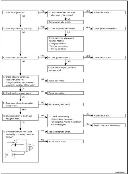
Work Flow
OVERALL SEQUENCE
DETAILED FLOW
NOTE
:
If any malfunction is found, immediately disconnect the battery cable from the
negative terminal.
1.CHECK ENGINE START
Crank the engine and check that the engine starts.
Does the engine start? YES >> GO TO 2.
NO >> GO TO 3.
2.CHECK THAT THE STARTER MOTOR STOPS
Check that the starter motor stops after starting the engine.
Does the starter motor stop? YES >> INSPECTION END
NO >> Replace magnetic switch.
3.CHECK THE ENGINE SPEED WITH CRANKING
Check that the engine runs at cranking.
Does engine turn by cranking? YES >> GO TO 4.
NO >> GO TO 5.
4.CHECK THE ENGINE SPEED WITH CRANKING
Check that the engine speed is not low at cranking.
Does engine turn normally? YES >> Check ignition/fuel system.
NO >> Check charge condition, corrosion and connection condition of the battery. Refer to PG-113, "Work Flow".
5.CHECK STARTER MOTOR ACTIVATION
Check that the starter motor runs at cranking.
Does starter motor turn? YES >> GO TO 6.
NO >> GO TO 7.
6.CHECK STARTER MOTOR UNIT
1. Remove starter motor.
2. Check that the gear shaft of starter motor rotates.
Does gear shaft turn? YES >> Check pinion clutch. Refer to STR-24, "HR16DE : Inspection and Adjustment" (HR16DE) or STR- 30, "MR16DDT : Inspection and Adjustment" (MR16DDT).
NO >> Check reduction gear, armature and gear shaft.
7.CHECK POWER SUPPLY CIRCUIT
Check the following conditions.
• Fuse and fusible link
• Charge condition, corrosion and connection condition of the battery. Refer to PG-113, "Work Flow".
Are these inspection results normal? YES >> GO TO 8.
NO >> Repair as needed.
8.CHECK STARTING SYSTEM WIRING
Check the following.
• “B” terminal circuit. Refer to STR-17, "Diagnosis Procedure".
• “S” terminal circuit. Refer to STR-19, "Diagnosis Procedure".
Are these inspection results normal? YES >> GO TO 9.
NO >> Repair as needed.
9.CHECK MAGNETIC SWITCH OPERATION SOUND
Check that a magnetic switch operation sound can be heard when the ignition switch is set at the starting position.
Does magnetic switch operation sound occur? YES >> GO TO 10.
NO >> Replace magnetic switch.
10.PINION AND RING GEAR ENGAGEMENT CHECK
Check condition of pinion and ring gear mesh.
Is the inspection result normal? YES >> GO TO 12.
NO >> GO TO 11.
11.CHECK STARTER MOTOR UNIT
Check the following.
• Adjust pinion movement. Refer to STR-24, "HR16DE : Inspection and Adjustment" (HR16DE) or STR-30, "MR16DDT : Inspection and Adjustment" (MR16DDT).
• Check pinion moving mechanism.
• Check ring gear.
Are these inspection results normal? YES >> INSPECTION END
NO >> Repair or replace, if necessary.
12.CHECK STARTER MOTOR UNIT
Check that the starter motor runs when connecting the positive terminal (12 V) to starter motor terminal M and the negative terminal (ground) to starter motor body.
Does the starter motor run? YES >> Replace magnetic switch.
NO >> Repair starter motor.
 Starting system (without intelligent key)
CVT : Wiring Diagram
For connector terminal arrangements, harness layouts, and alphabets in a
(option abbreviation; if not
described in wiring diagram), refer to GI-12, "Connector Information/ ...

Other materials:
Power supply and ground circuit
Diagnosis Procedure
1.INSPECTION START
Start engine.
Is engine running?
YES >> GO TO 6.
NO >> GO TO 2.
2.CHECK GROUND CONNECTION-I
1. Turn ignition switch OFF.
2. Check ground connection E38. Refer to Ground Inspection in GI-44, "Circuit
Inspection".
Is the i ...
Precaution Necessary for Steering Wheel Rotation after Battery Disconnect
NOTE:
• Before removing and installing any control units, first turn the ignition
switch to the LOCK position, then disconnect
both battery cables.
• After finishing work, confirm that all control unit connectors are connected
properly, then re-connect both
battery cables.
• Always use CONS ...
A/C indicator
Diagnosis Procedure
1.CHECK SYMPTOM
Check symptom.
A/C indicator dose not turn ON>>GO TO 2.
A/C indicator dose not turn OFF>>GO TO 6.
2.CHECK FUSE
1. Turn ignition switch OFF.
2. Check 10A fuse (No. 15, located in fuse block (J/B)].
NOTE:
Refer to PG-22, "Fuse, Conn ...
