Nissan Juke Service and Repair Manual : Back door request switch
Component Function Check
1.CHECK FUNCTION
1. Select “INTELLIGENT KEY” of “BCM” using CONSULT-III.
2. Select “REQ SW-BD/TR” in “DATA MONITOR” mode.
3. Check that the function operates normally according to the following conditions.
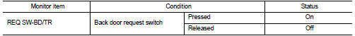
Is the inspection result normal? YES >> Back door request switch is OK.
NO >> Refer to DLK-246, "Diagnosis Procedure".
Diagnosis Procedure
1.CHECK BACK DOOR REQUEST SWITCH INPUT SIGNAL
1. Turn ignition switch OFF.
2. Disconnect back door opener switch connector.
3. Check voltage between back door opener switch harness connector and ground.
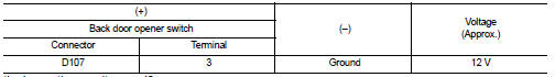
Is the inspection result normal? YES >> GO TO 3.
NO >> GO TO 2.
2.CHECK BACK DOOR REQUEST SWITCH CIRCUIT
1. Disconnect BCM connector.
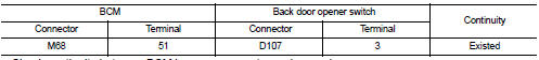
2. Check continuity between BCM harness connector and back door opener switch harness connector.
3. Check continuity between BCM harness connector and ground.
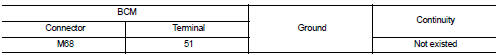
Is the inspection result normal? YES >> Replace BCM. Refer to BCS-93, "Removal and Installation".
NO >> Repair harness or connector.
3.CHECK BACK DOOR REQUEST SWITCH GROUND CIRCUIT
Check continuity between back door opener switch harness connector and ground.
Is the inspection result normal? YES >> GO TO 4.
NO >> Repair or replace harness.
4.CHECK BACK DOOR REQUEST SWITCH
Refer to DLK-247, "Component Inspection".
Is the inspection result normal? YES >> GO TO 5.
NO >> Replace back door opener switch.
5.CHECK INTERMITTENT INCIDENT
Refer to GI-42, "Intermittent Incident".
>> INSPECTION END
Component Inspection
1.CHECK BACK DOOR REQUEST SWITCH
1. Turn ignition switch OFF.
2. Disconnect back door opener switch connector.
3. Check continuity between back door opener switch terminals.
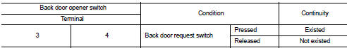
Is the inspection result normal? YES >> INSPECTION END
NO >> Replace back door opener switch.
 Back door opener switch
Component Function Check
1.CHECK FUNCTION
1. Select “TRUNK” of “BCM” using CONSULT-III.
2. Select “TR/BD OPEN SW” in “DATA MONITOR” mode.
3. Check that the function operates normally according to ...
 Buzzer (combination meter)
Component Function Check
1.CHECK FUNCTION
1. Select “INTELLIGENT KEY” of “BCM” using CONSULT-III.
2. Select “INSIDE BUZZER” in “ACTIVE TEST” mode.
3. Check that the function operates normally acco ...
Other materials:
Oil pan
Exploded View
1. Baffle plate
2. Gasket
3. Oil pan
4. O-ring
5. Drain plug
6. Oil level gauge guide
7. Transaxle
8. Crankshaft position sensor (POS)
: N·m (kg-m, ft-lb)
: N·m (kg-m, in-lb)
: Always replace after every
disassembly.
Removal and Installation
REMOVAL
CAUTION:
Nev ...
P2122, P2123 APP sensor
DTC Logic
DTC DETECTION LOGIC
NOTE:
If DTC P2122 or P2123 is displayed with DTC P0643, first perform the trouble
diagnosis for DTC P0643.
Refer to EC-307, "DTC Logic".
DTC CONFIRMATION PROCEDURE
1.PRECONDITIONING
If DTC Confirmation Procedure has been previously conducted, alw ...
Power supply and ground circuit
Diagnosis Procedure
1.CHECK 4WD CONTROL MODULE POWER SUPPLY (1)
1. Turn the ignition switch OFF.
2. Disconnect 4WD control module harness connector.
3. Check the voltage between 4WD control module harness connector and ground.
4. Turn the ignition switch ON.
CAUTION:
Never start the engin ...
