Nissan Juke Service and Repair Manual : B26F5 steering lock status switch
DTC Logic
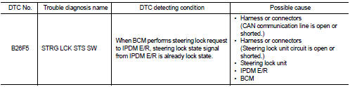
DTC DETECTION LOGIC
NOTE
:
• If DTC B26F5 is displayed with DTC U1000, first perform the trouble diagnosis
for DTC U1000. Refer to
BCS-83, "DTC Logic".
• If DTC B26F5 is displayed with DTC U1010, first perform the trouble diagnosis for DTC U1010. Refer to BCS-84, "DTC Logic".
DTC CONFIRMATION PROCEDURE
1.PERFORM DTC CONFIRMATION PROCEDURE
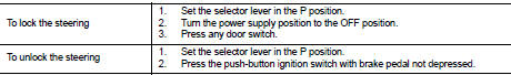
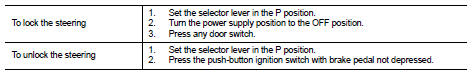
1. Shift selector lever to the P position.
2. Turn ignition switch ON.
3. Turn ignition switch OFF.
4. Press driver side door switch.
5. Check DTC in “Self Diagnostic Result” mode of “BCM” using CONSULT-III.
Is DTC detected? YES >> Go to SEC-123, "Diagnosis Procedure".
NO >> INSPECTION END
Diagnosis Procedure
1.CHECK IPDM E/R INPUT SIGNAL
1. Turn ignition switch OFF.
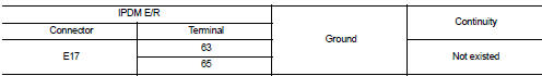
2. Check voltage between IPDM E/R harness connector and ground.
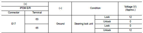
NOTE:
Is the inspection result normal? YES >> GO TO 4.
NO >> GO TO 2.
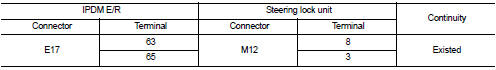
2.CHECK IPDM E/R INPUT SIGNAL CIRCUIT
1. Disconnect IPDM E/R connector and steering lock unit connector.
2. Check continuity between IPDM E/R harness connector and steering lock unit harness connector.
3. Check continuity between IPDM E/R harness connector and ground.
Is the inspection result normal? YES >> GO TO 3.
NO >> Repair or replace harness.
3.REPLACE STEERING LOCK UNIT
1. Replace steering lock unit.
2. Perform the service procedure for steering lock unit replacement. Refer to CONSULT-III Operation Manual NATS-IVIS/NVIS.
>> INSPECTION END
4.CHECK BCM INPUT SIGNAL
1. Turn ignition switch OFF.
2. Check voltage between BCM harness connector and ground.
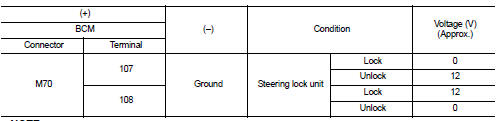
NOTE:
Is the inspection result normal? YES >> GO TO 5.
NO >> GO TO 6.
5.REPLACE BCM
1. Replace BCM. Refer to BCS-93, "Removal and Installation".
2. Perform initialization of BCM and registration of all Intelligent Keys using CONSULT-III.
For initialization and registration procedures, refer to CONSULT-III Operation Manual NATS-IVIS/NVIS.
>> INSPECTION END
6.CHECK BCM INPUT SIGNAL CIRCUIT
1. Disconnect BCM connector and steering lock unit connector.
2. Check continuity between BCM harness connector and steering lock unit harness connector.
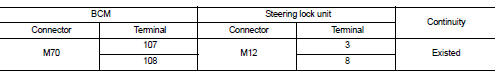
3. Check continuity between BCM harness connector and ground.

Is the inspection result normal? YES >> GO TO 7.
NO >> Repair or replace harness.
7.REPLACE STEERING LOCK UNIT
1. Replace steering lock unit.
2. Perform the service procedure for steering lock unit replacement. Refer to CONSULT-III Operation Manual NATS-IVIS/NVIS.
>> INSPECTION END
 B26F4 starter control relay
DTC Logic
DTC DETECTION LOGIC
NOTE:
• If DTC B26F4 is displayed with DTC U1000, first perform the trouble diagnosis
for DTC U1000. Refer to
BCS-83, "DTC Logic".
• If DTC B26F4 is disp ...
 B26F7 BCM
DTC Logic
DTC DETECTION LOGIC
DTC CONFIRMATION PROCEDURE
1.PERFORM DTC CONFIRMATION PROCEDURE
1. Press door request switch.
2. Turn ignition switch ON.
3. Check DTC in “Self Diagnostic Result” ...
Other materials:
Line pressure test
Work Procedure
INSPECTION
1. Check the engine oil level. Replenish if necessary. LU-25, "Inspection".
2. Check for leak of the CVT fluid. Refer to TM-480, "Inspection".
3. Drive for about 10 minutes to warm up the vehicle so that the CVT fluid
temperature is 50 to 80°C (122 ...
Front wiper motor hi circuit
Component Function Check
1.CHECK FRONT WIPER HI OPERATION
CONSULT-III ACTIVE TEST
1. Select “FRONT WIPER” of IPDM E/R active test item.
2. With operating the test item, check front wiper operation.
Hi : Front wiper (HI) operation
Off : Stop the front wiper
Is front wiper (HI) operation normal ...
A/C switch
Component Function Check
1.CHECK A/C ON SIGNAL
With CONSULT-III
1. Turn ignition switch ON.
2. Select “AIR CONDITIONER” of “BCM” using CONSULT-III.
3. Select “AIR COND SW” in “DATA MONITOR” mode, and check status under the
following condition.
Is the inspection result normal?
YES >> ...
