Nissan Juke Service and Repair Manual : B2626 outside antenna
DTC Logic
DTC DETECTION LOGIC
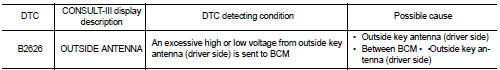
DTC CONFIRMATION PROCEDURE
1.PERFORM DTC CONFIRMATION PROCEDURE
1. Disconnect outside key antenna (driver side) connector.
2. Perform “INTELLIGENT KEY” Self Diagnostic Result.
Is outside key antenna DTC detected? YES >> Refer to DLK-61, "Diagnosis Procedure".
NO >> Outside key antenna (driver side) is OK.
Diagnosis Procedure
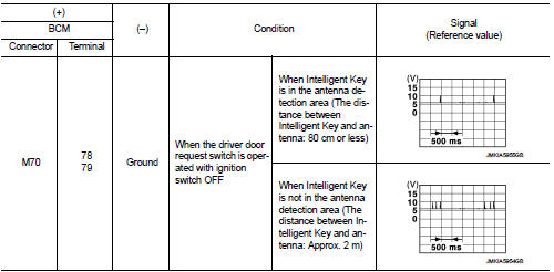
1.CHECK OUTSIDE KEY ANTENNA INPUT SIGNAL 1
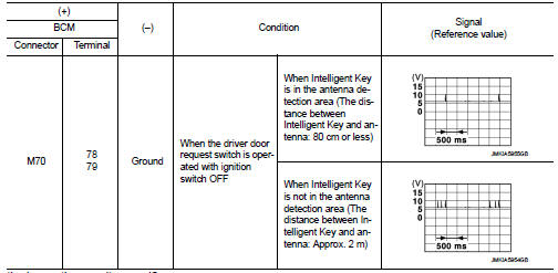
1. Turn ignition switch OFF.
2. Check signal between BCM harness connector and ground using oscilloscope.
Is the inspection result normal? YES >> Replace BCM. Refer to BCS-93, "Removal and Installation".
NO >> GO TO 2.
2.CHECK OUTSIDE KEY ANTENNA CIRCUIT
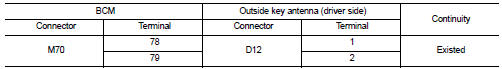
1. Disconnect BCM connector and outside key antenna (driver side) connector.
2. Check continuity between BCM harness connector and outside key antenna (driver side) harness connector.
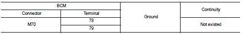
3. Check continuity between BCM harness connector and ground.
Is the inspection result normal? YES >> GO TO 3.
NO >> Repair or replace harness.
3.CHECK OUTSIDE KEY ANTENNA INPUT SIGNAL 2
1. Replace outside key antenna (driver side). (New antenna or other
antenna)
2. Connect BCM connector and outside key antenna (driver side) connector.
3. Check signal between BCM harness connector and ground using oscilloscope.
Is the inspection result normal? YES >> Replace outside key antenna (driver side).
NO >> Replace BCM. Refer to BCS-93, "Removal and Installation".
 B2623 inside antenna
DTC Logic
DTC DETECTION LOGIC
DTC CONFIRMATION PROCEDURE
1.PERFORM DTC CONFIRMATION PROCEDURE
1. Select “INTELLIGENT KEY” of “BCM” using CONSULT-III.
2. Select “INSIDE ANT DIAGNOSIS” in “WORK S ...
 B2627 outside antenna
DTC Logic
DTC DETECTION LOGIC
DTC CONFIRMATION PROCEDURE
1.PERFORM DTC CONFIRMATION PROCEDURE
1. Disconnect outside key antenna (passenger side) connector.
2. Perform “INTELLIGENT KEY” Self Dia ...
Other materials:
A-bag branch line circuit
Diagnosis Procedure
WARNING:
• Before servicing, turn ignition switch OFF, disconnect battery negative
terminal, and wait 3 minutes
or more. (To discharge backup capacitor.)
• Never use unspecified tester or other measuring device.
1.CHECK CONNECTOR
1. Turn the ignition switch OFF.
2. Disco ...
Emission control not satisfactory
Description
CHART 22: EMISSION CONTROL NOT SATISFACTORY
Diagnosis Procedure
1.CHECK ECM POWER SUPPLY AND GROUND CIRCUIT
Check ECM power supply and ground circuit. Refer to EC-885, "Diagnosis
Procedure".
Is the inspection result normal?
YES >> GO TO 2.
NO >> Repair ...
Wiring diagram
IPDM E/R
Wiring Diagram
For connector terminal arrangements, harness layouts, and alphabets in a
(option abbreviation; if not
described in wiring diagram), refer to GI-12, "Connector Information/Explanation
of Option Abbreviation".
...
