Nissan Juke Service and Repair Manual : B2620 Park/neutral position switch
DTC Logic
DTC DETECTION LOGIC
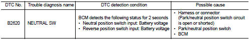
DTC CONFIRMATION PROCEDURE
1.PERFORM DTC CONFIRMATION PROCEDURE
1. Turn ignition switch ON and wait 2 seconds or more under the following conditions.
2. Set shift lever in the Neutral position and wait for 2 seconds or more.
3. Set shift lever in the Reverse position and wait for 2 seconds or more.
4. Check DTC in “Self Diagnostic Result” mode of “BCM” using CONSULT-III.
Is DTC detected? YES >> Go to SEC-110, "Diagnosis Procedure".
NO >> INSPECTION END
Diagnosis Procedure
1.CHECK PARK/NEUTRAL POSITION SWITCH POWER SUPPLY
1. Turn ignition switch OFF.
2. Disconnect park/neutral position switch connector.
3. Turn ignition switch ON.
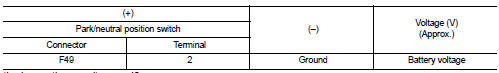
4. Check voltage between park/neutral position switch harness connector and ground.
Is the inspection result normal? YES >> GO TO 2.
NO-1 >> Check 10 A fuse [No. 5, located in the fuse block (J/B)].
NO-2 >> Check harness for open or short between park/neutral position switch and fuse.
2.CHECK NEUTRAL POSITION SWITCH SIGNAL
1. Turn ignition switch OFF.
2. Connect park/neutral position switch connector.
3. Turn ignition switch ON.
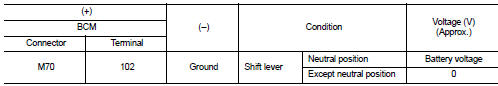
4. Check voltage between BCM harness connector and ground
Is the inspection result normal? YES >> GO TO 4.
NO >> GO TO 3.
3.CHECK NEUTRAL POSITION SWITCH SIGNAL CIRCUIT
1. Turn ignition switch OFF.
2. Disconnect park/neutral position switch connector.
3. Disconnect BCM connector.
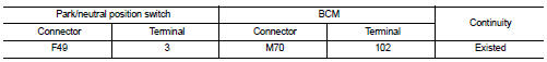
4. Check continuity between park/neutral position switch harness connector and BCM harness connector.
5. Check continuity between park/neutral position switch harness connector and ground.
Is the inspection result normal? YES >> GO TO 6.
NO >> Repair or replace harness.
4.CHECK REVERSE POSITION SWITCH SIGNAL
Check voltage between BCM harness connector and ground.
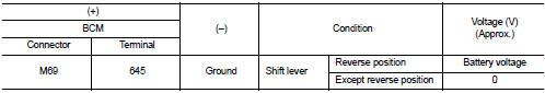
Is the inspection result normal? YES >> GO TO 8.
NO >> GO TO 5.
5.CHECK REVERSE POSITION SWITCH SIGNAL CIRCUIT
1. Turn ignition switch OFF.
2. Disconnect park/neutral position switch connector.
3. Disconnect BCM connector.
4. Check continuity between park/neutral position switch harness connector and BCM harness connector.
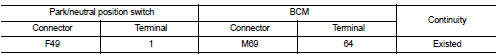
5. Check continuity between park/neutral position switch harness connector and ground.
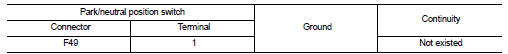
Is the inspection result normal? YES >> GO TO 6.
NO >> Repair or replace harness.
6.CHECK PARK/NEUTRAL POSITION SWITCH
Refer to SEC-112, "Component Inspection".
Is the inspection result normal? YES >> GO TO 7.
NO >> Replace park/neutral position switch. Refer to TM-24, "Removal and Installation". (5MT: RS5F92R) or TM-77, "Removal and Installation" (6MT: RS6F94R).
7.CHECK INTERMITTENT INCIDENT
Refer to GI-42, "Intermittent Incident".
>> INSPECTION END
8.REPLACE BCM
1. Replace BCM. Refer to BCS-93, "Removal and Installation".
2. Perform initialization of BCM and reregistration of all Intelligent Key using CONSULT-III.
For initialization and reregistration procedures, refer to CONSULT-III Operation Manual NATS-IVIS/NVIS.
>> INSPECTION END
Component Inspection
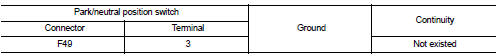
1.CHECK PARK/NEUTRAL POSITION SWITCH
1. Turn ignition switch OFF.
2. Disconnect park/neutral position switch connector.
3. Check continuity between park/neutral position switch terminals under the following conditions.
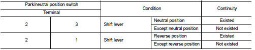
Is the inspection result normal? YES >> INSPECTION END
NO >> Replace park/neutral position switch. Refer to TM-24, "Removal and Installation". (5MT: RS5F92R) or TM-77, "Removal and Installation" (6MT: RS6F94R).
 B261F ASCD clutch switch
DTC Logic
DTC DETECTION LOGIC
NOTE:
• If DTC B261F is displayed with DTC U1000, first perform the trouble diagnosis
for DTC U1000. Refer to
BCS-83, "DTC Logic".
• If DTC B261F is disp ...
 B26E8 clutch interlock switch
DTC Logic
NOTE:
• If DTC B26E8 is displayed with DTC B210F, first perform the trouble diagnosis
for DTC B210F. Refer to
BCS-83, "DTC Logic".
• If DTC B26E8 is displayed with DTC B2110, ...
Other materials:
Precaution for Supplemental Restraint System (SRS) "AIR BAG" and "SEAT BELT
PRE-TENSIONER"
The Supplemental Restraint System such as “AIR BAG” and “SEAT BELT
PRE-TENSIONER”, used along
with a front seat belt, helps to reduce the risk or severity of injury to the
driver and front passenger for certain
types of collision. Information necessary to service the system safely is
include ...
Electrical load signal
Description
The electrical load signal (Headlamp switch signal, rear window defogger
switch signal, etc.) is transferred to
ECM through the CAN communication line.
Component Function Check
1.CHECK REAR WINDOW DEFOGGER SWITCH FUNCTION
1. Turn ignition switch ON.
2. Select “DATA MONITOR” mode ...
ECM branch line circuit
Diagnosis Procedure
1.CHECK CONNECTOR
1. Turn the ignition switch OFF.
2. Disconnect the battery cable from the negative terminal.
3. Check the terminals and connectors of the ECM for damage, bend and loose
connection (unit side and
connector side).
Is the inspection result normal?
YES &g ...
