Nissan Juke Service and Repair Manual : B261A push-button ignition switch
DTC Logic
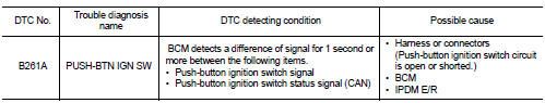
DTC DETECTION LOGIC
NOTE
:
• If DTC B261A is displayed with DTC U1000, first perform the trouble diagnosis
for DTC U1000. Refer to
BCS-83, "DTC Logic".
• If DTC B261A is displayed with DTC U1010, first perform the trouble diagnosis for DTC U1010. Refer to BCS-84, "DTC Logic".
DTC CONFIRMATION PROCEDURE
1.PERFORM DTC CONFIRMATION PROCEDURE
1. Press the push-button ignition switch under the following conditions, and wait for 1 second or more.
CVT models
- Selector lever is in the P or N position
- Do not depress brake pedal
M/T models
- Do not depress clutch pedal
2. Check “Self-diagnosis result” of BCM with CONSULT-III.
Is DTC detected? YES >> Go to PCS-101, "Diagnosis Procedure".
NO >> INSPECTION END
Diagnosis Procedure
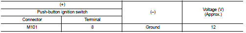
1.CHECK IGNITION SWITCH OUTPUT SIGNAL (PUSH-BUTTON IGNITION SWITCH)
1. Disconnect push-button ignition switch connector and IPDM E/R connector.
2. Check voltage between push-button ignition switch harness connector and ground.
Is the inspection result normal? YES >> GO TO 3.
NO >> GO TO 2.
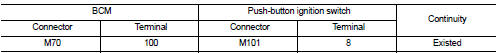
2.CHECK PUSH-BUTTON IGNITION SWITCH CIRCUIT (BCM)
1. Disconnect BCM connector.
2. Check continuity between BCM harness connector and push-button ignition switch harness connector.
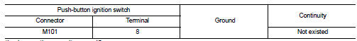
3. Check continuity between push-button ignition switch harness connector and ground.
Is the inspection result normal? YES >> Replace BCM. Refer to BCS-93, "Removal and Installation".
NO >> Repair or replace harness.
3.CHECK IGNITION SWITCH OUTPUT SIGNAL (IPDM E/R)
Check voltage between IPDM E/R harness connector and ground.
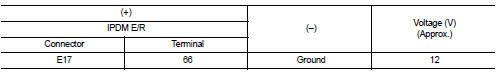
Is the inspection result normal? YES >> Replace IPDM E/R.
NO >> GO TO 4.
4.CHECK PUSH-BUTTON IGNITION SWITCH CIRCUIT (IPDM E/R)
1. Disconnect BCM connector.
2. Check continuity between IPDM E/R harness connector and push-button ignition switch harness connector.
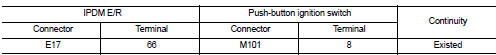
3. Check continuity between push-button ignition switch harness connector and ground.
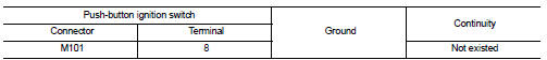
Is the inspection result normal? YES >> GO TO 5.
NO >> Repair or replace harness.
5.CHECK INTERMITTENT INCIDENT
Refer to GI-42, "Intermittent Incident".
>> INSPECTION END
 B2618 BCM
DTC Logic
DTC DETECTION LOGIC
NOTE:
• If DTC B2618 is displayed with DTC U1000, first perform the trouble diagnosis
for DTC U1000. Refer to
BCS-83, "DTC Logic".
• If DTC B2618 is disp ...
 B26F1 ignition relay
DTC Logic
DTC DETECTION LOGIC
DTC CONFIRMATION PROCEDURE
1.PERFORM DTC CONFIRMATION PROCEDURE
1. Turn ignition switch ON under the following conditions, and wait for 2
seconds or more.
CVT ...
Other materials:
Precaution
Precaution for Supplemental Restraint System (SRS) "AIR BAG" and "SEAT
BELT
PRE-TENSIONER"
The Supplemental Restraint System such as “AIR BAG” and “SEAT BELT PRE-TENSIONER”,
used along
with a front seat belt, helps to reduce the risk or severity of injury to the
driver a ...
Driver air bag module
Exploded View
1. Steering column upper cover
2. Steering column assembly
3. Steering column lower cover
4. Side lid LH
5. TORX bolt
6. Driver air bag module
7. TORX bolt
8. Side lid RH
9. Steering wheel
10. Spiral cable
11. Steering angle sensor
12. Combination switch
13. Stee ...
Key ID warning does not operate
Diagnosis Procedure
1.CHECK DTC WITH BCM AND COMBINATION METER
Check that DTC is not detected with BCM and combination meter.
Is the inspection result normal?
YES >> GO TO 2.
NO-1 >> Refer to BCS-67, "DTC Index". (BCM)
NO-2 >> Refer to MWI-36, "DTC Index&qu ...
