Nissan Juke Service and Repair Manual : B261A Push-button ignition switch
DTC Logic
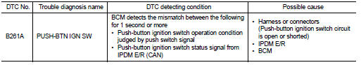
DTC DETECTION LOGIC
NOTE
:
• If DTC B261A is displayed with DTC U1000, first perform the trouble diagnosis
for DTC U1000. Refer to
BCS-83, "DTC Logic".
• If DTC B261A is displayed with DTC U1010, first perform the trouble diagnosis for DTC U1010. Refer to BCS-84, "DTC Logic".
DTC CONFIRMATION PROCEDURE
1.PERFORM DTC CONFIRMATION PROCEDURE
1. Press push-button ignition switch for 1 second under the following condition .
- Selector lever: In the P position - Brake pedal: Not depressed 2. Release push-button ignition switch and wait 1 second.
3. Check DTC in “Self diagnostic result” mode of “BCM” using CONSULT-III.
Is DTC detected? YES >> Go to SEC-106, "Diagnosis Procedure" NO >> INSPECTION END
Diagnosis Procedure
1.CHECK PUSH-BUTTON IGNITION SWITCH POWER SUPPLY CIRCUIT
1. Turn ignition switch OFF.
2. Disconnect push-button ignition switch connector.
3. Disconnect IPDM E/R connector.
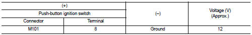
4. Check voltage between push-button ignition switch harness connector and ground.
Is the inspection result normal? YES >> GO TO 2.
NO >> GO TO 3.
2.CHECK PUSH-BUTTON IGNITION SWITCH CIRCUIT 1
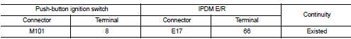
1. Check continuity between push-button ignition switch harness connector and IPDM E/R harness connector.
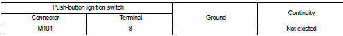
2. Check continuity between push-button ignition switch harness connector and ground.
Is the inspection result normal? YES >> Replace IPDM E/R. Refer to PCS-34, "Removal and Installation".
NO >> Repair harness or connector.
3.CHECK PUSH-BUTTON IGNITION SWITCH CIRCUIT 2
1. Disconnect BCM connector.
2. Check continuity between push-button ignition switch harness connector and BCM harness connector.
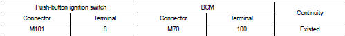
3. Check continuity between push-button ignition switch harness connector and ground.
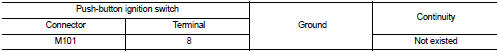
Is the inspection result normal? YES >> GO TO 4.
NO >> Repair harness or connector.
4.REPLACE BCM
1. Replace BCM. Refer to BCS-93, "Removal and Installation".
2. Perform initialization of BCM using CONSULT-III.
For initialization procedure, refer to CONSULT-III Operation Manual NATS-IVIS/NVIS.
>> INSPECTION END
 B2619 BCM
DTC Logic
DTC DETECTION LOGIC
DTC CONFIRMATION PROCEDURE
1.PERFORM DTC CONFIRMATION PROCEDURE
1. Press push-button ignition switch under the following conditions and wait
1 second or more.
- ...
 B261F ASCD clutch switch
DTC Logic
DTC DETECTION LOGIC
NOTE:
• If DTC B261F is displayed with DTC U1000, first perform the trouble diagnosis
for DTC U1000. Refer to
BCS-83, "DTC Logic".
• If DTC B261F is disp ...
Other materials:
Diagnosis system (EPS control unit)
Consult-III Function
FUNCTION
CONSULT-III can display each diagnostic item using the diagnostic test modes
shown following.
*: The following diagnosis information is erased by erasing.
• DTC
• Freeze frame data (FFD)
ECU IDENTIFICATION
Displays the part number stored in the control unit.
...
Liquid Gasket
REMOVAL OF LIQUID GASKET SEALING
• After removing mounting nuts and bolts, separate the mating surface
using the seal cutter [SST: KV10111100] (A) and remove old
liquid gasket sealing.
CAUTION:
Be careful not to damage the mating surfaces.
• Tap the seal cutter [SST: KV10111100] to insert it ...
B1065, B1070 passenger air bag module
DTC Logic
DTC DETECTION LOGIC
DTC CONFIRMATION PROCEDURE
1.CHECK SELF-DIAG RESULT
With CONSULT-III
1. Turn ignition switch ON.
2. Perform “Self Diagnostic Result” mode of “AIR BAG” using CONSULT-III.
Without CONSULT-III
1. Turn ignition switch ON.
2. Check the air bag warning lamp statu ...
