Nissan Juke Service and Repair Manual : B2190 nats antenna AMP
DTC Logic
DTC DETECTION LOGIC
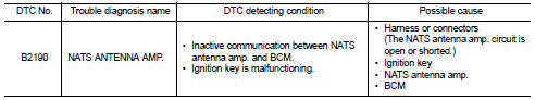
DTC CONFIRMATION PROCEDURE
1.PERFORM DTC CONFIRMATION PROCEDURE
1. Turn ignition switch ON.
2. Check DTC in “Self Diagnostic Result” mode of “BCM” using CONSULT-III.
Is DTC detected? YES >> Refer to SEC-200, "Diagnosis Procedure".
NO >> INSPECTION END
Diagnosis Procedure
1.CHECK FUSE
Check that the following IPDM E/R fuse is not blown.

Is the fuse fusing? YES >> Replace the blown fuse after repairing the affected circuit if a fuse is blown.
NO >> GO TO 2.
2.CHECK NATS ANTENNA AMP. INSTALLATION
Check NATS antenna amp. Installation. Refer to SEC-233, "Removal and Installation".
Is the inspection result normal? YES >> GO TO 3.
NO >> Reinstall NATS antenna amp. correctly.
3.CHECK IGNITION KEY
Start engine using another registered ignition key.
Does the engine start? YES-1 >> Replace ignition key.
YES-2 >> Perform initialization of BCM and reregistration of all ignition keys using CONSULT-III. For initialization and registration procedures, refer to CONSULT-III Operation Manual NATS-IVIS/NVIS.
NO >> GO TO 4.
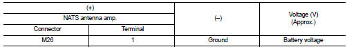
4.CHECK NATS ANTENNA AMP. POWER SUPPLY
1. Turn ignition switch OFF.
2. Disconnect NATS antenna amp. connector.
3. Check voltage between NATS antenna amp. harness connector and ground.
Is the inspection result normal? YES >> GO TO 6.
NO >> GO TO 5.
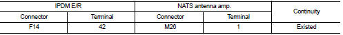
5.CHECK NATS ANTENNA AMP. POWER SUPPLY CIRCUIT
1. Disconnect IPDM E/R connector.
2. Check continuity between IPDM E/R harness connector and NATS antenna amp. connector.
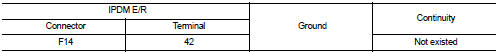
3. Check continuity between IPDM E/R harness connector and ground.
Is the inspection result normal? YES >> Replace IPDM E/R. Refer to PCS-63, "Removal and Installation".
NO >> Repair or replace harness.
6.CHECK NATS ANTENNA AMP. GROUND CIRCUIT
Check continuity between NATS antenna amp. harness connector and ground.
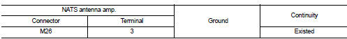
Is the inspection result normal? YES >> GO TO 7.
NO >> Repair or replace harness.
7.CHECK NATS ANTENNA AMP. SIGNAL
1. Connect BCM connector and NATS antenna amp. connector.
2. Check voltage between BCM harness connector and ground.
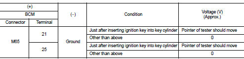
Is the inspection result normal? YES >> GO TO 9.
NO >> GO TO 8.
8.CHECK NATS ANTENNA AMP. SIGNAL CIRCUIT
1. Disconnect NATS antenna amp. connector.
2. Check continuity between BCM harness connector and NATS antenna amp. harness connector.
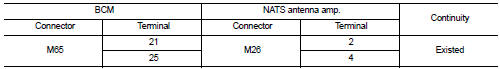
3. Check continuity between BCM harness connector and ground.
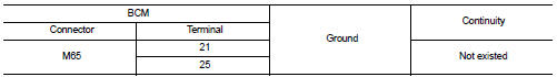
Is the inspection result normal? YES >> Replace NATS antenna amp. Refer to SEC-233, "Removal and Installation".
NO >> Repair or replace harness.
9.CHECK INTERMITTENT INCIDENT
Refer to GI-42, "Intermittent Incident".
>> INSPECTION END
 P1616 ECM
DTC Logic
DTC DETECTION LOGIC
DTC CONFIRMATION PROCEDURE
1.PERFORM DTC CONFIRMATION PROCEDURE FOR MALFUNCTION
1. Turn ignition switch ON amd wait 2 seconds or more.
2. Check DTC in “Self Diagno ...
 B2191 difference of key
DTC Logic
DTC DETECTION LOGIC
DTC CONFIRMATION PROCEDURE
1.PERFORM DTC CONFIRMATION PROCEDURE
1. Turn ignition switch ON.
2. Check DTC in “Self Diagnostic Result” mode of “BCM” using CONSULT-II ...
Other materials:
Antenna base
Exploded View
1. Antenna rod
2. Antenna base
: N·m (kg-m, in-lb)
Removal and Installation
REMOVAL
1. Remove headlining. Refer to INT-26, "Exploded View".
2. Disconnect antenna feeder connector.
3. Remove nut to remove antenna base.
INSTALLATION
Install in the reverse order o ...
P2138 APP sensor
DTC Logic
DTC DETECTION LOGIC
NOTE:
If DTC P2138 is displayed with DTC P0643, first perform the trouble diagnosis
for DTC P0643. Refer to
EC-307, "DTC Logic".
DTC CONFIRMATION PROCEDURE
1.PRECONDITIONING
If DTC Confirmation Procedure has been previously conducted, always perform ...
A/C indicator
Diagnosis Procedure
1.CHECK SYMPTOM
Check symptom.
A/C indicator dose not turn ON>>GO TO 2.
A/C indicator dose not turn OFF>>GO TO 6.
2.CHECK FUSE
1. Turn ignition switch OFF.
2. Check 10A fuse (No. 15, located in fuse block (J/B)].
NOTE:
Refer to PG-22, "Fuse, Conn ...
