Nissan Juke Service and Repair Manual : B210E starter relay
DTC Logic
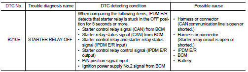
DTC DETECTION LOGIC
NOTE
:
• If DTC B210E is displayed with DTC U1000, first perform the trouble diagnosis
for DTC U1000. Refer to
PCS-30, "DTC Logic".
• If DTC B210E is displayed with DTC B2605, first perform the trouble diagnosis for DTC B2605. Refer to SEC-90, "DTC Logic".
• When IPDM E/R power supply voltage is low (Approx. 7 - 8 V for about 1 second), the DTC B210E may be detected.
DTC CONFIRMATION PROCEDURE
1.PERFORM DTC CONFIRMATION PROCEDURE
1. Press push-button ignition switch under the following conditions to start engine, and wait 5 seconds or more.
- Selector lever: In the P position - Brake pedal: Depressed 2. Check DTC in “Self Diagnostic Result” mode of “IPDM E/R” using CONSULT-III.
Is DTC detected? YES >> Go to SEC-148, "Diagnosis Procedure".
NO >> GO TO 2.
2.PERFORM DTC CONFIRMATION PROCEDURE 2
1. Stop engine.
2. Perform DTC CONFIRMATION PROCEDURE for DTC P1650. Refer to EC-366, "DTC Logic" (MR16DDT) or EC-725, "DTC Logic" (HR16DE).
3. Turn ignition switch ON.
4. Check DTC in “Self Diagnostic Result” mode of “IPDM E/R” using CONSULT-III.
Is DTC detected? YES >> Refer to SEC-146, "Diagnosis Procedure".
NO >> INSPECTION END
Diagnosis Procedure
1.INSPECTION START
Perform inspection in accordance with procedure that confirms DTC.
Which procedure confirms DTC? DTC confirmation procedure 1>>GO TO 2.
DTC confirmation procedure 2>>GO TO 5.
2.CHECK STARTER RELAY OUTPUT SIGNAL
1. Check voltage between BCM harness connector and ground.
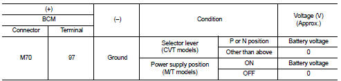
Is the inspection result normal? YES >> GO TO 4.
NO >> GO TO 3.
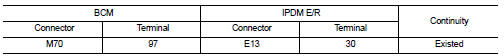
3.CHECK STARTER RELAY OUTPUT SIGNAL CIRCUIT
1. Turn ignition switch OFF.
2. Disconnect BCM connector.
3. Disconnect IPDM E/R connector.
4. Check continuity between BCM harness connector and IPDM E/R harness connector.
5. Check continuity between BCM harness connector and ground.
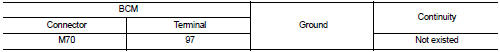
Is the inspection result normal? YES >> Replace IPDM E/R. Refer to PCS-34, "Removal and Installation".
NO >> Repair or replace harness.
4.CHECK STARTER RELAY CIRCUIT
1. Turn ignition switch OFF.
2. Disconnect IPDM E/R connector.
3. Check voltage between IPDM E/R harness connector and ground.
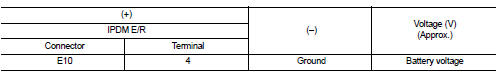
Is the inspection result normal? YES >> GO TO 7.
NO >> Check harness for open or short between IPDM E/R and battery. Refer to PCS-27, "Wiring Diagram".
5.CHECK IGNITION POWER SUPLLY NO.2 SIGNAL
1. Turn ignition switch OFF.
2. Disconnect IPDM E/R connector.
3. Check voltage between IPDM E/R harness connector and ground.
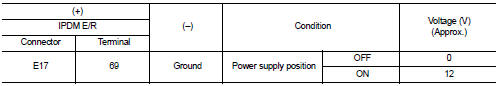
Is the inspection result normal? YES >> Replace IPDM E/R. Refer to PCS-34, "Removal and Installation".
NO >> GO TO 6.
6.CHECK BCM INPUT SIGNAL CIRCUIT
1. Disconnect BCM connector.
2. Check continuity between IPDM E/R harness connector and BCM harness connector.
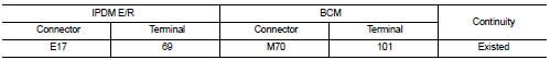
3. Check continuity between transmission range switch harness connector and ground.
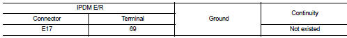
Is the inspection result normal? YES >> GO TO 7.
NO >> Repair or replace harness.
7.REPLACE BCM
1. Replace BCM. Refer to BCS-93, "Removal and Installation".
2. Perform DTC CONFIRMATION PROCEDURE for DTC B210E. Refer to SEC-148, "DTC Logic".
Is the inspection result normal? YES >> INSPECTION END
NO >> Replace IPDM E/R. Refer to PCS-34, "Removal and Installation".
 B210D starter relay
DTC Logic
DTC DETECTION LOGIC
NOTE:
If DTC B210D is displayed with DTC U1000, first perform the trouble diagnosis
for DTC U1000. Refer to PCS-
30, "DTC Logic".
DTC CONFIRMATION PROC ...
 B210F shift position/clutch interlock switch
DTC Logic
DTC DETECTION LOGIC
NOTE:
If DTC B210F is displayed with DTC U1000, first perform the trouble diagnosis
for DTC U1000. Refer to PCS-
30, "DTC Logic".
DTC CONFIRMATION PROC ...
Other materials:
Evaporative emission system
Inspection
1. Visually inspect EVAP vapor lines for improper attachment and for cracks,
damage, loose connections,
chafing and deterioration.
2. Check EVAP canister as follows:
a. Block port (A). Orally blow air through port (B).
Check that air flows freely through port (C).
b. Block port (B ...
Maintenance precautions
When performing any inspection or maintenance work on your vehicle, always take
care to prevent serious accidental injury to yourself or damage to the vehicle.
The following are general precautions which should be closely observed.
WARNING
• Park the vehicle on a level surface, apply the ...
U0140 lost communication (BCM)
Description
CAN (Controller Area Network) is a serial communication line for real-time
application. It is an on-vehicle multiplex
communication line with high data communication speed and excellent malfunction
detection ability.
Many electronic control units are equipped onto a vehicle, and ...
