Nissan Juke Service and Repair Manual : B210C starter control relay
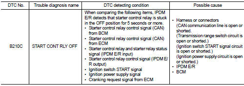
DTC Logic
DTC DETECTION LOGIC
NOTE
:
• If DTC B210C is displayed with DTC U1000, first perform the trouble diagnosis
for DTC U1000. Refer to
PCS-30, "DTC Logic".
• When IPDM E/R power supply voltage is low (Approx. 7 - 8 V for about 1 second), the DTC B210C may be detected.
DTC CONFIRMATION PROCEDURE
1.PERFORM DTC CONFIRMATION PROCEDURE 1
1. Press push-button ignition switch under the following conditions to start engine, and wait 5 seconds or more.
- Selector lever: In the P position - Brake pedal: Depressed 2. Check DTC in “Self Diagnostic Result” mode of “IPDM E/R” using CONSULT-III.
Is DTC detected? YES >> Go to SEC-215, "Diagnosis Procedure".
NO >> GO TO 2.
2.PERFORM DTC CONFIRMATION PROCEDURE 2
1. Stop engine.
2. Perform DTC CONFIRMATION PROCEDURE for DTC P1650. Refer to EC-366, "DTC Logic" (MR16DDT) or EC-725, "DTC Logic" (HR16DE).
3. Turn ignition switch ON.
4. Check DTC in “Self Diagnostic Result” mode of “IPDM E/R” using CONSULT-III.
Is DTC detected? YES >> Refer to SEC-215, "Diagnosis Procedure".
NO >> INSPECTION END
Diagnosis Procedure
1.INSPECTION START
Perform inspection in accordance with procedure that confirms DTC.
Which procedure confirms DTC? DTC confirmation procedure 1>>GO TO 2.
DTC confirmation procedure 2>>GO TO 7.
2.CHECK DTC OF BCM
Check DTC in “Self Diagnostic Result” mode of “BCM” using CONSULT-III.
Is DTC detected? YES >> Perform the trouble diagnosis related to the detected DTC. Refer to BCS-67, "DTC Index".
NO >> GO TO 3.
3.CHECK DTC OF TCM
Check DTC in “Self Diagnostic Result” mode of “TRANSMISSION” using CONSULT-III.
Is DTC detected? YES >> Perform the trouble diagnosis related to the detected DTC. Refer to TM-171, "DTC Index" (CVT: RE0F10B) or TM-366, "DTC Index" (CVT: RE0F11A).
NO >> GO TO 4.
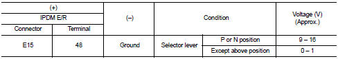
4.CHECK TRANSMISSION RANGE SWITCH SIGNAL
1. Turn ignition switch ON.
2. Check voltage between IPDM E/R harness connector and ground.
Is the inspection result normal? YES >> GO TO 5.
NO >> Repair or replace harness. Refer to STR-12, "CVT : Wiring Diagram".
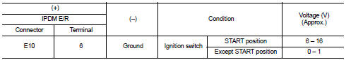
5.CHECK IGNITION SWITCH START SIGNAL
1. Turn ignition switch OFF.
2. Disconnect IPDM E/R harness connector.
3. Check voltage between IPDM E/R harness connector and ground.
Is the inspection result normal? YES >> GO TO 6.
NO >> Repair or replace harness. Refer to STR-12, "CVT : Wiring Diagram".
6.PERFORM DTC CONFIRMATION PROCEDURE AGAIN
1. Reconnect IPDM E/R harness connector.
2. Turn ignition switch ON.
3. Select “Self Diagnostic Result” mode of “IPDM E/R” using CONSULT-III.
4. Touch “ERASE”.
5. Perform DTC CONFIRMATION PROCEDURE for DTC B210C. Refer to SEC-215, "DTC Logic".
Is DTC detected? YES >> Replace IPDM E/R. Refer to PCS-63, "Removal and Installation".
NO >> INSPECTION END
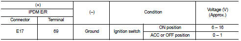
7.CHECK IGNITION POWER SUPPLY SIGNAL
1. Turn ignition switch OFF.
2. Disconnect IPDM E/R harness connector.
3. Check voltage between IPDM E/R harness connector and ground.
Is the inspection result normal? YES >> Replace IPDM E/R. Refer to PCS-63, "Removal and Installation".
NO >> Repair or replace harness. Refer to STR-12, "CVT : Wiring Diagram".
 B210B starter control relay
DTC Logic
DTC DETECTION LOGIC
NOTE:
If DTC B210B is displayed with DTC U1000, first perform the trouble diagnosis
for DTC U1000. Refer to PCS-
30, "DTC Logic".
DTC CONFIRMATION PROC ...
 B210D starter relay
DTC Logic
DTC DETECTION LOGIC
NOTE:
• If DTC B210D is displayed with DTC U1000, first perform the trouble diagnosis
for DTC U1000. Refer to
PCS-59, "DTC Logic".
• If DTC B210D is disp ...
Other materials:
Spark plug
Removal and Installation
REMOVAL
1. Remove ignition coil. Refer to EM-178, "Exploded View".
2. Remove spark plug with a spark plug wrench (commercial service
tool).
a : 14 mm (0.55 in)
CAUTION:
Never drop or shock spark plug.
INSTALLATION
Install in the reverse order of removal ...
Inspection
INSPECTION AFTER INSTALLATION
• Check accelerator pedal moves smoothly within the whole operation range
when it is fully depressed and
released.
• Check accelerator pedal securely returns to the fully released position.
• For the electrical inspection of accelerator pedal position sensor. Refe ...
Structure and operation
Sectional View
1. 3rd input gear
2. 3rd-4th synchronizer hub assembly
3. 4th input gear
4. 5th input gear
5. 5th-6th synchronizer hub assembly
6. 6th input gear
7. Transaxle case
8. 6th main gear
9. 5th main gear
10. 4th main gear
11. 3rd main gear
12. 2nd main gear
13. 1st-2n ...
