Nissan Juke Service and Repair Manual : B20A0 cranking request circuit
DTC Logic
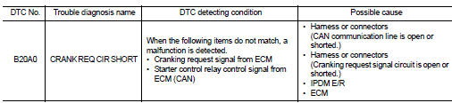
DTC DETECTION LOGIC
NOTE
:
If DTC B20A0 is displayed with DTC U1000, first perform the trouble diagnosis
for DTC U1000. Refer to PCS-
59, "DTC Logic".
DTC CONFIRMATION PROCEDURE
1.PERFORM DTC CONFIRMATION PROCEDURE
1. Perform DTC CONFIRMATION PROCEDURE for DTC P1650. Refer to EC-366, "DTC Logic" (MR16DDT) or EC-725, "DTC Logic" (HR16DE).
2. Turn ignition switch ON.
3. Check DTC in “Self Diagnostic Result” mode of “IPDM E/R” using CONSULT-III.
Is DTC detected? YES >> Refer to SEC-211, "Diagnosis Procedure".
NO >> INSPECTION END
Diagnosis Procedure
1.CHECK CRANKING REQUEST SIGNAL
1. Turn ignition switch ON.
2. Check voltage between IPDM E/R harness connector and ground under the following conditions.
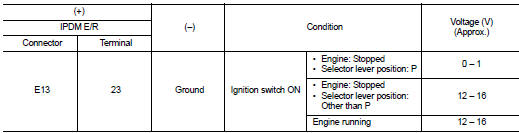
Is the inspection result normal? YES >> GO TO 3.
NO >> GO TO 2.
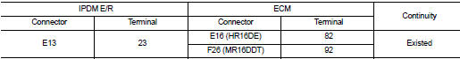
2.CHECK CRANKING REQUEST SIGNAL CIRCUIT
1. Turn ignition switch OFF.
2. Disconnect IPDM E/R connector.
3. Disconnect ECM connector.
4. Check continuity between IPDM E/R harness connector and ECM harness connector.
5. Check continuity between BCM harness connector and ground.
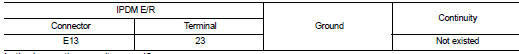
Is the inspection result normal? YES >> GO TO 3.
NO >> Repair or replace harness.
3.REPLACE IPDM E/R
1. Replace IPDM E/R. Refer to PCS-63, "Removal and Installation".
2. Perform DTC CONFIRMATION PROCEDURE for DTC B20A0. Refer to SEC-211, "DTC Logic".
Is DTC detected? YES >> GO TO 4.
NO >> INSPECTION END
4.REPLACE ECM
Replace ECM.
Refer to EC-447, "Removal and Installation" (MR16DDT) or EC-805, "Removal and Installation" (HR16DE).
>> INSPECTION END
 B209f cranking request circuit
DTC Logic
DTC DETECTION LOGIC
NOTE:
If DTC B209F is displayed with DTC U1000, first perform the trouble diagnosis
for DTC U1000. Refer to PCS-
59, "DTC Logic".
DTC CONFIRMATION PROC ...
 B210B starter control relay
DTC Logic
DTC DETECTION LOGIC
NOTE:
If DTC B210B is displayed with DTC U1000, first perform the trouble diagnosis
for DTC U1000. Refer to PCS-
30, "DTC Logic".
DTC CONFIRMATION PROC ...
Other materials:
On board diagnostic (OBD) system
Diagnosis Description
DESCRIPTION
The CVT system has two self-diagnostic systems.
The first is the emission-related on board diagnostic system (OBD) performed by
the TCM in combination with
the ECM. The malfunction is indicated by the MIL (malfunction indicator lamp)
and is stored as a DTC ...
Air conditioner filter
Exploded View
LHD models
1. A/C unit assembly
2. Air conditioner filter
3. Filter cover
Removal and Installation (LHD models)
REMOVAL
1. Remove glove box assembly. Refer to IP-13, "Removal and Installation".
2. Remove filter cover (1), and then remove air conditioner filter (2) ...
Diagnosis system (combination meter)
On Board Diagnosis Function
ON BOARD DIAGNOSIS ITEM
The combination meter allows the following diagnosis items with the on-board
diagnosis function.
METHOD OF STARTING
1. Turn ignition switch ON, and switch the trip meter to “trip A” or “trip
B”.
2. Turn ignition switch OFF.
3. While pre ...
