Nissan Juke Service and Repair Manual : B1042, B1043, B1044, B1045, B1046, B1047 diagnosis sensor unit
DTC Logic
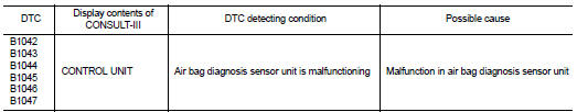
DTC DETECTION LOGIC
DTC CONFIRMATION PROCEDURE
1.CHECK SELF-DIAG RESULT
 With CONSULT-III
1. Turn ignition switch ON.
2. Perform “Self Diagnostic Result” mode of “AIR BAG” using CONSULT-III.
 Without CONSULT-III
1. Turn ignition switch ON.
2. Check the air bag warning lamp status. Refer to SRC-12, "On Board Diagnosis Function".
NOTE
:
SRS does not enter the diagnosis mode if no malfunction is detected in the user
mode.
Is malfunctioning part detected? YES >> Refer to SRC-44, "Diagnosis Procedure".
NO >> INSPECTION END
Diagnosis Procedure
WARNING:
• Before servicing, turn ignition switch OFF, disconnect battery negative
terminal, and wait 3 minutes
or more. (To discharge backup capacitor.)
• Never use unspecified tester or other measuring device.
1.CHECK HARNESS CONNECTOR
Check the harness connector.
Is the inspection result normal? YES >> GO TO 2.
NO >> Replace harness connectors.
2.CHECK WIRING HARNESS
Check the wiring harness externals.
Is the inspection result normal? YES >> GO TO 3.
NO >> Replace wiring harness.
3.REPLACE AIR BAG DIAGNOSIS SENSOR UNIT
1. Replace air bag diagnosis sensor unit. Refer to SR-30, "Removal and Installation".
2. Perform DTC confirmation procedure. Refer to SRC-44, "DTC Logic".
Is DTC detected? YES >> GO TO 1.
NO >> INSPECTION END
 B1037, B1039, B1041 crash zone sensor
DTC Logic
DTC DETECTION LOGIC
DTC CONFIRMATION PROCEDURE
1.CHECK SELF-DIAG RESULT
With CONSULT-III
1. Turn ignition switch ON.
2. Perform “Self Diagnostic Result” mode of “AIR BAG” using CONSU ...
 B1049, B1054 driver air bag module
DTC Logic
DTC DETECTION LOGIC
DTC CONFIRMATION PROCEDURE
1.CHECK SELF-DIAG RESULT
With CONSULT-III
1. Turn ignition switch ON.
2. Perform “Self Diagnostic Result” mode of “AIR BAG” using CONSU ...
Other materials:
Connector Information/Explanation of Option Abbreviation
CONNECTOR LIST
Connector information and harness layout are described in “POWER SUPPLY,
GROUND & CIRCUIT ELEMENTS”
Section.
EXPLANATION OF OPTION ABBREVIATION
HOW TO USE CONNECTOR INFORMATION
Description
...
Evaporative emission system
Inspection
1. Visually inspect EVAP vapor lines for improper attachment and for cracks,
damage, loose connections,
chafing and deterioration.
2. Check EVAP canister as follows:
a. Block port (A). Orally blow air through port (B).
Check that air flows freely through port (C).
b. Block port (B ...
Exhaust manifold
Exploded View
1. Stud bolt
2. Exhaust manifold cover
3. Exhaust manifold
4. Gasket
Engine front
: N·m (kg-m, ft-lb)
: N·m (kg-m, in-lb)
: Always replace after every
disassembly.
Removal and Installation
REMOVAL
1. Drain engine coolant. Refer to CO-11, "Draining".
2. Remo ...
