Nissan Juke Service and Repair Manual : ASCD main switch
Component Function Check
1.CHECK ASCD MAIN SWITCH FUNCTION
 With CONSULT-III
1. Turn ignition switch ON.
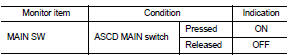
2. Select “MAIN SW” in “DATA MONITOR” mode of “ENGINE” using CONSULT-III.
3. Check “MAIN SW” indication as per the following condition.
 Without CONSULT-III
1. Turn ignition switch ON.
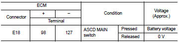
2. Check the voltage between ECM harness connector and ground as per the following conditions.
Is the inspection result normal? YES >> INSPECTION END
NO >> Proceed to EC-430, "Diagnosis Procedure".
Diagnosis Procedure
1.CHECK ASCD MAIN SWITCH POWER SUPPLY
1. Turn ignition switch OFF.
2. Disconnect combination switch (spiral cable) harness connector.
3. Turn ignition switch ON.
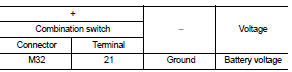
4. Check the voltage between combination switch harness connector and ground.
Is the inspection result normal? YES >> GO TO 2.
NO >> Perform the trouble diagnosis for power supply circuit.
2.CHECK ASCD MAIN SWITCH INPUT SIGNAL CIRCUIT
1. Turn ignition switch OFF.
2. Disconnect ECM harness connector.
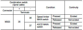
3. Check the continuity between ECM harness connector and combination switch harness connector.
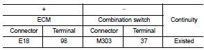
4. Also check harness for short to ground and to power.
Is the inspection result normal? YES >> GO TO 3.
NO >> Repair or replace error-detected parts.
3.CHECK ASCD STEERING SWITCH
Check the ASCD steering switch. Refer to EC-431, "Component Inspection".
Is the inspection result normal? YES >> Check intermittent incident. Refer to GI-42, "Intermittent Incident".
NO >> Replace ASCD steering switch. Refer to ST-9, "Exploded View".
Component Inspection
1.CHECK ASCD STEERING SWITCH-I
1. Disconnect combination switch (spiral cable) harness connector.
2. Check the continuity between combination switch harness connector terminals as per the following conditions.
Is the inspection result normal? YES >> INSPECTION END
NO >> Replace ASCD steering switch. Refer to ST-9, "Exploded View".
2.CHECK ASCD STEERING SWITCH
1. Disconnect combination switch (spiral cable) harness connector.
2. Check the resistance between combination switch harness connector terminals as per the following conditions.
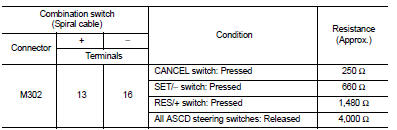
Is the inspection result normal? YES >> INSPECTION END
NO >> Replace ASCD steering switch. Refer to ST-9, "Exploded View".
 Clutch pedal position switch
Component Function Check
1.CHECK FOR CLUTCH PEDAL POSITION SWITCH FUNCTION
1. Turn ignition switch ON.
2. Check the voltage between ECM harness connector and ground.
Is the inspection result nor ...
 SPEED LIMITER MAIN SWITCH
Component Function Check
1.CHECK SPEED LIMITER MAIN SWITCH FUNCTION
With CONSULT-III
1. Turn ignition switch ON.
2. Select “SL MAIN SW” in “DATA MONITOR” mode of “ENGINE” using CONSULT-III.
3. Ch ...
Other materials:
Control buttons
The control buttons for the Bluetooth® Hands- Free Phone System are located on
the steering wheel.
PHONE SEND
Push the button to initiate a VR
session or answer an incoming call.
You can also use the button to
interrupt system feedback and give a command at once.
PHONE END
While the ...
Remote keyless entry system
System Diagram
System Description
DOOR LOCK AND UNLOCK OPERATION
• When door lock and unlock button of keyfob is pressed, door lock and unlock
signal transmits from keyfob to
BCM via remote keyless entry receiver.
• When BCM receives the door lock and unlock signal, it operates door lock
...
P183A coupling temperature sensor right
DTC Logic
DTC DETECTION LOGIC
DTC CONFIRMATION PROCEDURE
1.PRECONDITIONING
If “DTC CONFIRMATION PROCEDURE” has been previously conducted, always turn
ignition switch OFF and
wait at least 10 seconds before conducting the next test.
>> GO TO 2.
2.DTC REPRODUCTION PROCEDURE
With ...
