Nissan Juke Service and Repair Manual : Adjustment of steering angle sensor neutral position
Description
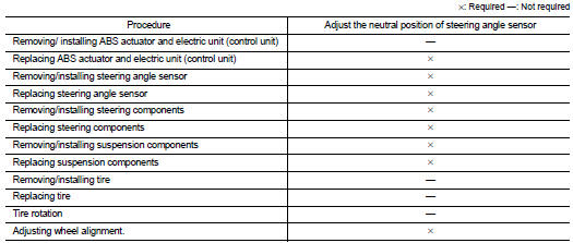
Always adjust the neutral position of steering angle sensor before driving when the following operation is performed.
Work Procedure
ADJUST THE NEUTRAL POSITION OF STEERING ANGLE SENSOR
CAUTION:
Always use CONSULT-III when adjusting the neutral position of steering angle
sensor. (It cannot be
adjusted other than with CONSULT-III.)
1.CHECK THE VEHICLE STATUS
Stop vehicle with front wheels in the straight-ahead position.
Does the vehicle stay in the straight-ahead position? YES >> GO TO 2.
NO >> Steer the steering wheel to the straight-ahead position. Stop the vehicle.
2.ADJUST NEUTRAL POSITION OF STEERING ANGLE SENSOR
 With CONSULT-III.
1. Turn the ignition switch ON.
CAUTION:
Never start engine.
2. Select “ABS”, “WORK SUPPORT” and “ST ANGLE SENSOR ADJUSTMENT” in this order.
3. Select “START”.
CAUTION:
Never touch steering wheel while adjusting steering angle sensor.
4. After approx. 10 seconds, select “END”.
5. Turn ignition switch OFF, and then turn it ON again.
CAUTION:
Be sure to perform the operation above.
>> GO TO 3.
3.CHECK DATA MONITOR
 With CONSULT-III.
1. The vehicle is either pointing straight ahead, or the vehicle needs to be moved. Stop when it is pointing straight ahead.
2. Select “ABS”, “DATA MONITOR”, “ECU INPUT SIGNALS” and “STR ANGLE SIG” in the order. Check that the signal is within the specified value.
STR ANGLE SIG : 0±2.5°
Is the inspection result normal? YES >> GO TO 4.
NO >> GO TO 1.
4.ERASE SELF-DIAGNOSIS MEMORY
With CONSULT-III.
Erase Self-diagnosis result of “ABS”.
Are the memories erased? YES >> INSPECTION END
NO >> Check the items indicated by the self-diagnosis.
 Additional service when replacing ABS actuator and electric
unit (control unit)
Additional service when replacing ABS actuator and electric
unit (control unit)
Description
When replaced the ABS actuator and electric unit (control unit), Perform
decel G sensor calibration. Refer to
BRC-149, "Work Procedure". ...

Other materials:
Vehicle security alarm does not activate
Description
Alarm does not operate when alarm operating condition is satisfied.
NOTE:
Check that vehicle is under the condition shown in “CONDITIONS OF VEHICLE
(OPERATING CONDITIONS)”
before starting diagnosis, and check each symptom.
CONDITION OF VEHICLE (OPERATING CONDITIONS)
“SECURITY ...
Microphone signal circuit
Description
Power is supplied from NAVI control unit to microphone. The microphone
transmits the sound voice to the
NAVI control unit.
Diagnosis Procedure
1.CHECK CONTINUITY BETWEEN NAVI CONTROL UNIT AND MICROPHONE CIRCUIT
1. Turn ignition switch OFF.
2. Disconnect NAVI control unit connecto ...
Door request switch
Component Function Check
1.CHECK FUNCTION
1. Select “INTELLIGENT KEY” of “BCM” using CONSULT-III.
2. Select “REQ SW-DR”, “REQ SW-AS” in “DATA MONITOR” mode.
3. Check that the function operates normally according to the following
conditions.
Is the inspection result normal?
YES >> Fro ...
